Jump takeoff position indicator system

a technology of position indicator and jump, which is applied in the direction of optical radiation measurement, gymnastic exercise, instruments, etc., can solve the problems of difficulty in determining the position of the foot in relation to the edge, the need for a coach or second athlete, and the cost of replacing the entire set of mechanical markers with the mechanical markers, etc., to save battery power, easy to remove and recharge or repla

Inactive Publication Date: 2007-06-26
RUBACH JAMES E
View PDF19 Cites 7 Cited by
  • Summary
  • Abstract
  • Description
  • Claims
  • Application Information

AI Technical Summary

Benefits of technology

[0022]The emitting and detecting devices are placed on the approach runway on opposite sides of the takeoff board and aligned with the leading or trailing edge of the board. When an athlete's foot makes contact with the takeoff board during a jump, one or more beams are broken. The detecting device detects the beams interruption, illuminates corresponding LED indicators, and stores the information for subsequent recall. The LED indicators are turned OFF to conserve battery power after a short time delay. When the recall switch is pressed, the stored position information is displayed on the LED indicators for several seconds. This feature allows the athlete to complete their jump and take as much time as needed to exit the landing pit and not loose the jump's takeoff position information. After the recall time delay, the system returns to scanning for the next jump and deletes the previous information from memory.
[0024]By utilizing wide angle beam emitters and detectors, along with collimating emitting and detecting apertures, a system is provided that does not require an accurate setup or alignment procedure but yet functions under all lighting conditions without adjustment. The number of beams used in a system is determined by the desired detection zone as well as the desired spacing between sensors. The system can easily be moved between takeoff boards without any modification of the approach runway or complicated setup procedure.
[0025]The invention also provides a low battery detection and indication system. The batteries are easily removed and recharged or replaced.

Problems solved by technology

However, it is difficult for the athlete to know where their foot was in relation to the edge of the takeoff board during these practice sessions while running at full speed and concentrating on the other aspects of the jump.
This often results in a coach or second athlete being needed to watch for the takeoff point.
This results in approximate takeoff positions at best as human error comes into play.
Several problems exist with this approach.
With up to 6 different takeoff boards needed for the long jump and triple jump runways, it would be very costly to replace them all with the mechanical marker board.
The marker board also presents a safety problem for the athlete as the foot is required to come in contact with movable elements.
A third problem involves the mechanical nature of the device.
With the location outdoors in close proximity to sand, the device would be a constant maintenance problem.
However, this system fails to provide the accuracy required by today's athletes.
This system also suffers from a very involved alignment and setup procedure utilizing mounting plates and adjustment screws.
Furthermore, the system lacks the portability required to move from location to location quickly as required when athletes are jumping from different takeoff boards.

Method used


Image

  • Jump takeoff position indicator system
  • Jump takeoff position indicator system
  • Jump takeoff position indicator system

Examples


Embodiment Construction

[0039]Throughout the following detailed description, the same reference numerals refer to the same elements in all figures. In addition, the terms microcontroller, CPU and processor are used interchangeably.

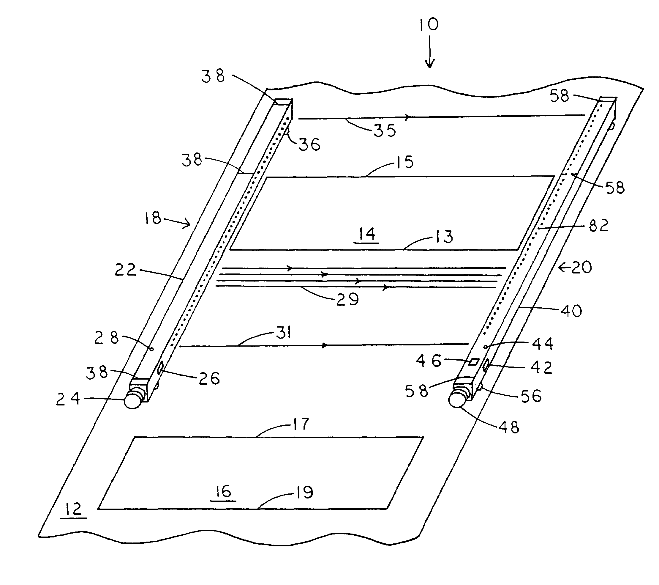
[0040]FIG. 1 illustrates a perspective view of the jump takeoff position indicator system 10. Approach runway 12 is provided with main takeoff board 14 and auxiliary board 16 for the athlete to jump from.

[0041]Emitting device 18 and detecting device 20 are placed on runway 12 on opposite sides of main takeoff board 14 with alignment marks 38 and 58 placed over foul line 15 or board leading edge 13. If auxiliary takeoff board 16 is used, the emitting and detecting devices are placed on opposite sides of auxiliary board 16 with alignment marks 38 and 58 placed directly above foul line 17 or board leading edge 19. Multiple alignment marks 38 and 58 are provided for setting up a detection zone in front of the takeoff board, on the takeoff board, or past the takeoff board.

[0042]As sho...


PUM


Abstract

A jump takeoff position indicator system that discloses the point of takeoff of a long jump or triple jump in athletic competition or practice when an athlete's foot comes in contact with a takeoff board when beginning a jump. A plurality of light beams are emitted parallel to the edge of the takeoff board. The light beams are closely spaced, parallel to each other, and transverse to the direction of the jump. The foot position is known by the location of the beams broken at takeoff. A light beam detector detects interruption of the light beams by an athlete's foot and displays the takeoff position on a plurality of visible LEDs. The system provides a memory for storing the takeoff position and recall switch for retrieving and displaying the information after completion of the jump. The system is immune from ambient light disturbances and can easily be moved between multiple takeoff board locations. Microcontrollers are employed in a modular fashion for system control. Furthermore, the system is battery operated with low battery detection provided.

Description

CROSS-REFERENCE TO RELATED APPLICATIONS[0001]Not ApplicableSTATEMENT REGARDING FEDERALLY SPONSORED RESEARCH[0002]Not ApplicableREFERENCE TO SEQUENCE LISTING[0003]Not ApplicableBACKGROUND OF THE INVENTION[0004]This invention relates generally to Track & Field equipment and particularly to a jump takeoff position indicator system for use in events requiring an accurate indication of the foot position of an athlete at takeoff such as in the long jump and triple jump competitions.[0005]The long jump and triple jump events in Track & Field competition require the athlete to jump from a fixed takeoff board into a sand filled landing pit from a running start down an approach runway. The takeoff board may be an actual wood or composition board or simply a painted area on the approach runway. Typical long jump runways have 2 takeoff boards at different distances from the sand pit to accommodate athletes of different jumping ability. The triple jump runway may have 3 or 4 different takeoff bo...

Claims


Application Information

Patent Timeline
Patent Type & Authority Patents(United States)
IPC IPC(8): G01B11/14G01J5/00A63B5/00A63B6/02A63B71/06
CPCA63B5/00A63B71/0605A63B6/025A63B2244/082
Inventor RUBACH, JAMES E.
Owner RUBACH JAMES E
Why Eureka
Try Eureka