Sound system having a HF horn coaxially aligned in the mouth of a midrange horn

Active Publication Date: 2007-06-26
HARMAN INT IND INC
View PDF7 Cites 22 Cited by
  • Summary
  • Abstract
  • Description
  • Claims
  • Application Information

AI Technical Summary

Benefits of technology

[0008]A sound system is provided that groups a midrange horn with a high frequency (“HF”) horn. This grouping may, for example, increase the sound pressure level (“SPL”) of the sound system while minimizing interference problems. The sound system includes an HF horn coaxially coupled to a midrange horn, and two HF drivers aligned edge-to-edge. The sound system further includes two midrange drivers aligned edge-to-edge and coupled to the midrange horn. The edge-to-edge alignment of the two HF drivers is substantially perpendicular to the edge-to-edge alignment of the two midrange drivers. The HF horn may, for example, have a throat within the midrange horn. The sound system may also include two slots merging to form a common exit, where the common exit is coupled to the throat of the HF horn and the two HF drivers are coupled to the two slots. A method for grouping a plurality of midrange drivers and a plurality of high frequency drivers is also provided.
[0011]With the HF horn coaxially positioned within the mouth of the midrange horn, the size of the sound system may be reduced. This coaxial mounting may, for example, allow the off-axis interference (lobing) through the crossover region to be optimized equally in both the horizontal and vertical planes. As an example, two midrange drivers and two HF drivers may be arranged to sum coherently within the system's coverage angles. This arrangement may provide a 6 dB increase in the SPL as compared to a single driver, while minimizing acoustic crossover interference problems.

Problems solved by technology

With the long distance, however, attenuation may develop in the sound waves.
Overlapping sound waves, however, interfere with other sound waves.
Another problem may be reverberation within the auditorium due to sound waves bouncing off the walls, affecting the quality of the sound.
Such an arrangement helps to raise the SPL but there may still be a problem with interference as the drivers do not add up to produce the optimal SPL.

Method used


Image

  • Sound system having a HF horn coaxially aligned in the mouth of a midrange horn
  • Sound system having a HF horn coaxially aligned in the mouth of a midrange horn
  • Sound system having a HF horn coaxially aligned in the mouth of a midrange horn

Examples


Embodiment Construction

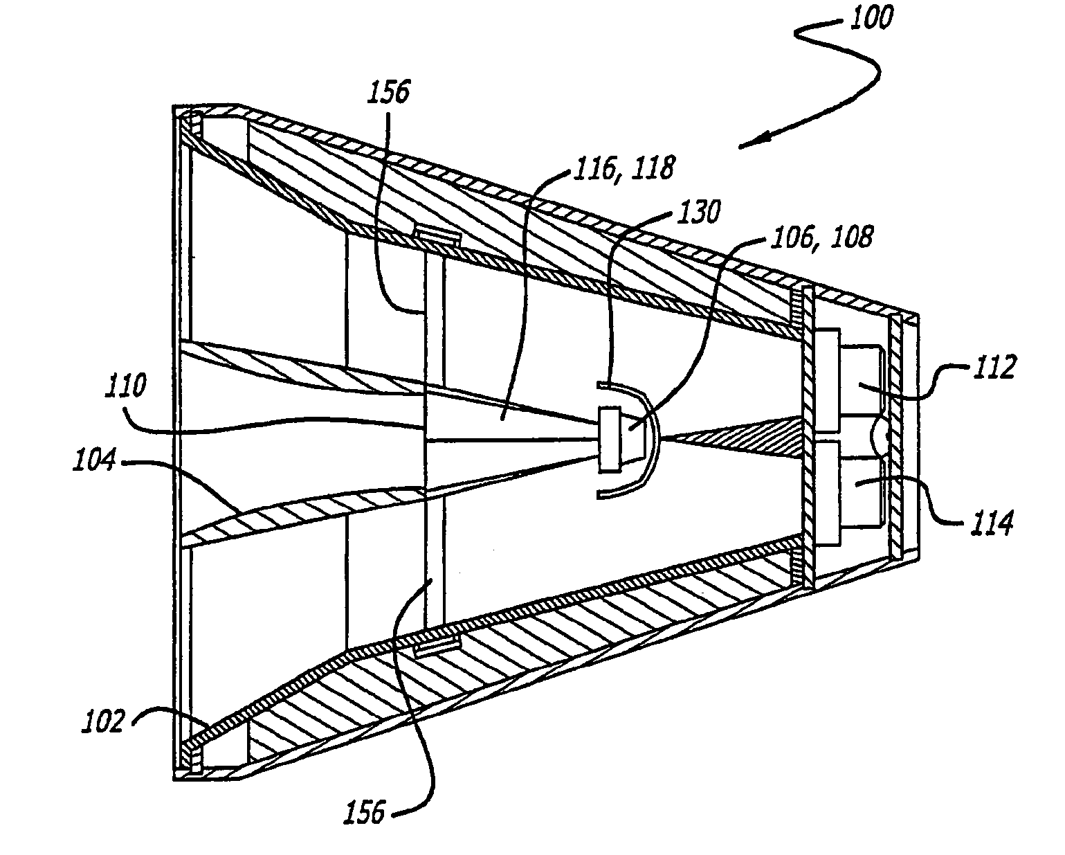
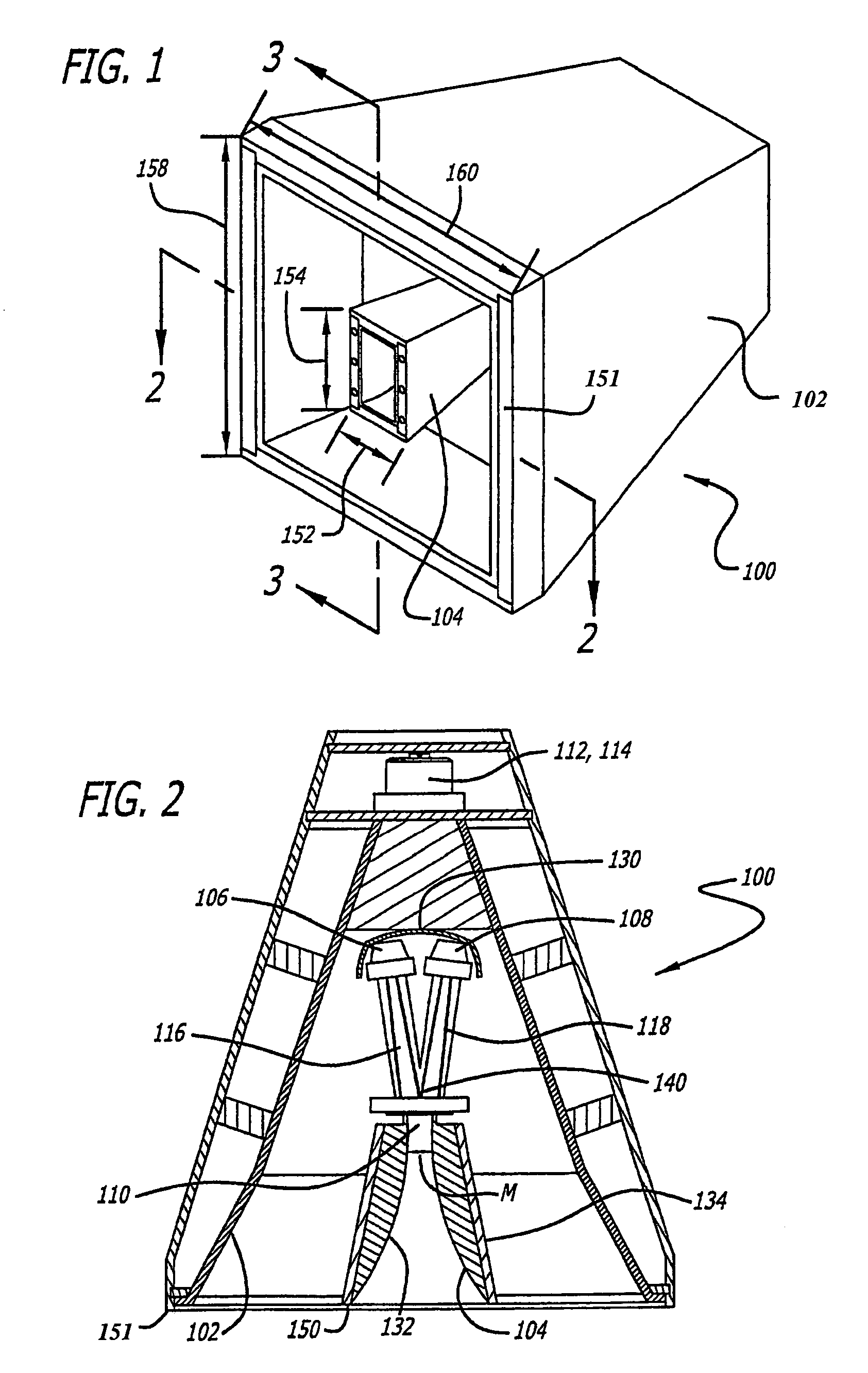
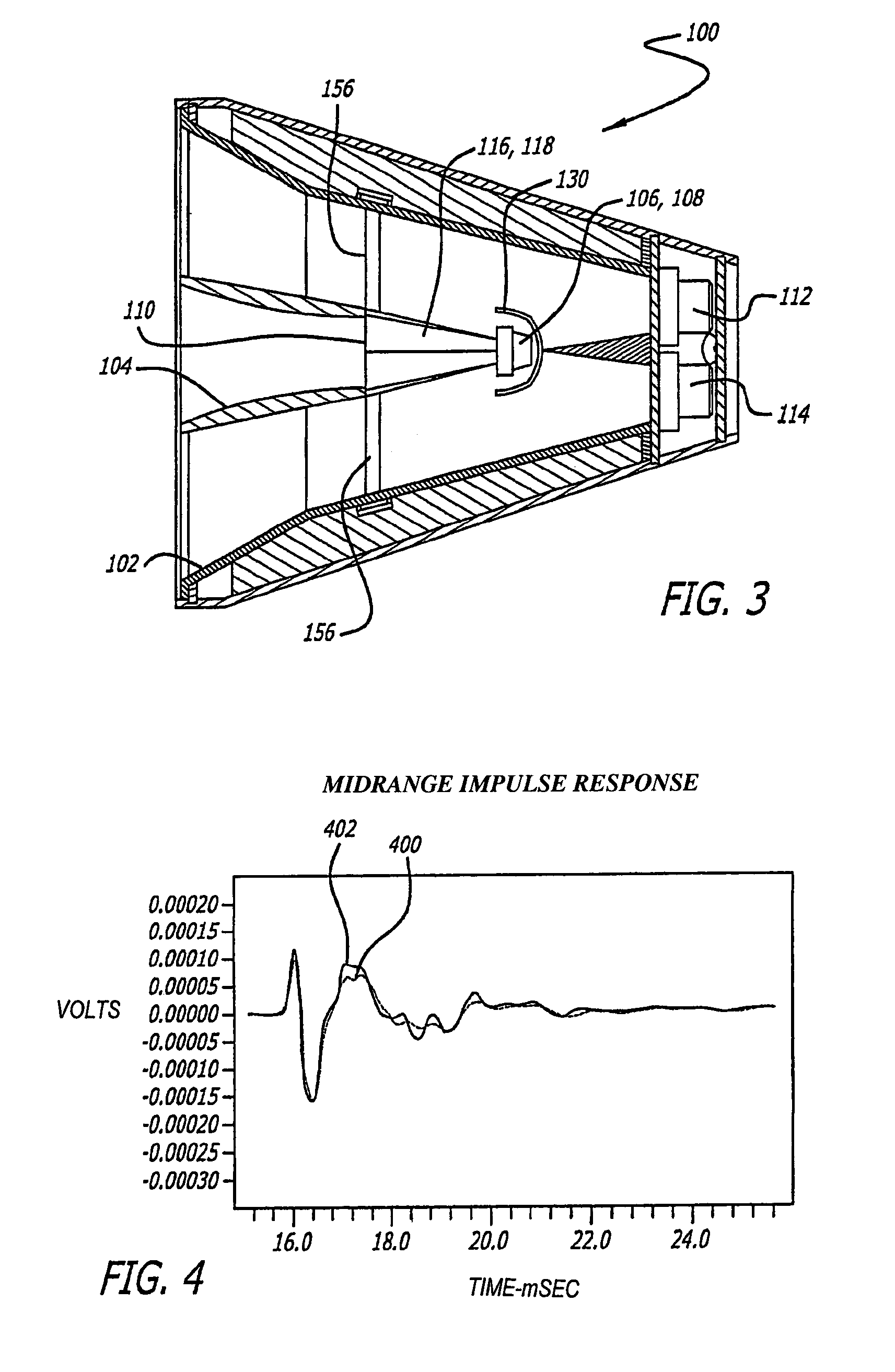
[0030]FIGS. 1 through 3 illustrate a sound system 100 incorporating a midrange horn 102 with a high frequency (HF) horn 104 that may increase the SPL while minimizing interference problems. FIG. 1 is a front view of the sound system 100 with high frequency horn 104 within midrange horn 102. FIG. 2 is a cross-sectional view of the sound system 100 along a line 2—2 of FIG. 1 showing a plurality of high frequency drivers 106, 108. FIG. 3 is a cross-sectional view of the sound system 100 along a line 3—3 of FIG. 1 showing a plurality of midrange drivers 112, 114. The sound system 100 may include the following features: (1) a HF horn 104 coupled to a plurality of high frequency drivers 106 and 108 where they sum or merge into a common throat 110 or wave guide; (2) coaxially mounting the midrange horn 102 with the HF horn 104, where the midrange horn 102 is coupled to a plurality of midrange drivers 112 and 114; and (3) mounting the plurality of midrange drivers 112 and 114 generally perp...


PUM


Abstract

A sound system is provided that groups a midrange horn with a high frequency (“H”) horn. The sound system includes an HF horn coaxially coupled to a midrange horn, and two HF drivers aligned edge-to-edge. The sound system further includes two midrange drivers aligned edge-to-edge and coupled to the midrange horn. The edge-to-edge alignment of the two HF drivers is substantially perpendicular to the edge-to-edge alignment of the two midrange drivers. A method for grouping a plurality of midrange drivers and a plurality of high frequency drivers is also provided. This configuration may produce increased sound pressure levels while minimizing acoustic crossover interference problems.

Description

CROSS REFERENCE TO RELATED APPLICATIONS[0001]This application claims priority of U.S. Provisional Patent Application Ser. No. 60 / 273,844, filed on Mar. 7, 2001, the entirety of which is incorporated by reference in this application.BACKGROUND OF THE INVENTION[0002]1. Field of the Invention[0003]This invention provides a sound system capable of grouping midrange and high frequency drivers together in an enclosure to increase the sound pressure level while minimizing interference problems.[0004]2. Related Art[0005]A sound system in a large spacious area such as an arena, outdoor, or stadium setting requires very high sound pressure levels (SPL) for adequate sound reproduction because of the long distances over which sound waves must travel in order to reach the listener. With the long distance, however, attenuation may develop in the sound waves. This may cause a drop of about 6 dB level of sound amplitude as sound waves travel twice the distances. Attenuation problems in the sound wa...

Claims


Application Information

Patent Timeline
IPC IPC(8): H04R1/02H04R1/26H04R1/30
CPCH04R1/26H04R1/30
Inventor WERNER, BERNARD M.
Owner HARMAN INT IND INC
Why Eureka
Try Eureka