System and method for graphically configuring leads

Inactive Publication Date: 2007-06-26
CARDIAC PACEMAKERS INC
View PDF15 Cites 14 Cited by
  • Summary
  • Abstract
  • Description
  • Claims
  • Application Information

AI Technical Summary

Benefits of technology

[0010]The present subject matter provides a programmer device that generally comprises circuitry for communicating with a medical device having lead(s) with electrode(s) in a configuration, and a display for graphically representing the configuration. In one embodiment, the display of the programmer device includes both a lead representation and an electrode representation. In various embodiments, the lead representation includes a lead position representation; and the electrode representation includes one or more of the following representations: an electrode position representation, a pulse polarity representation, and an electrical vector representation.
[0011]The present subject matter also provides a computer-readable medium encoded with a software program for providing a graphical display of a lead configuration for an implantable medical device. In one embodiment, for example, this software program operates in a memory of a programmer for a medical device. In other embodiments, the software program operates in a memory of another processing device, such as a computer. The software program executes the following: receiving information about a lead configuration, and graphically representing the lead configuration. In other embodiments, graphically representing the configuration includes graphically displaying one or more of the following representations:

Problems solved by technology

As medical devices provide more leads, electrodes per lead, and programming parameters for the leads, programming a configuration tends to become more complicated and confusing.
Due to discrepancies in the terminology and procedures used in the medical

Method used


Image

  • System and method for graphically configuring leads
  • System and method for graphically configuring leads
  • System and method for graphically configuring leads

Examples


Embodiment Construction

[0029]In the following detailed description, references are made to the accompanying drawings that illustrate specific embodiments in which the invention may be practiced. Changes in the electrical, mechanical, structural, logical or programming designs may be made to the embodiments without departing from the spirit and scope of the present invention. The following detailed description is, therefore, not to be taken in a limiting sense and the scope of the present invention is defined by the appended claims and their equivalents.

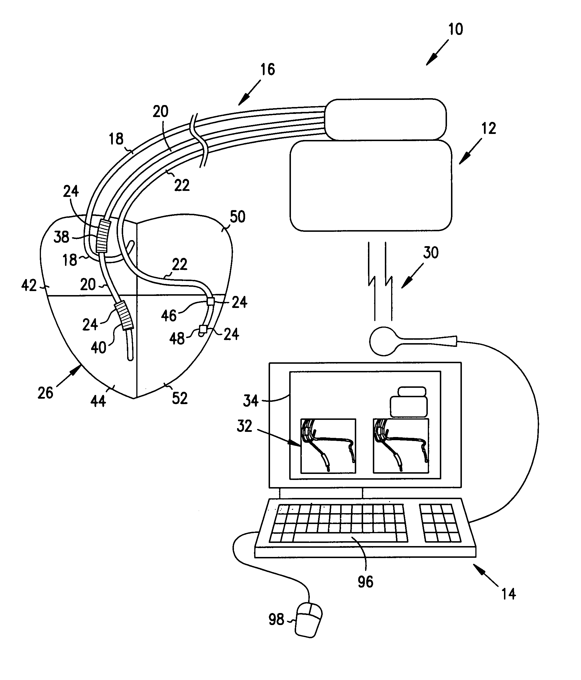
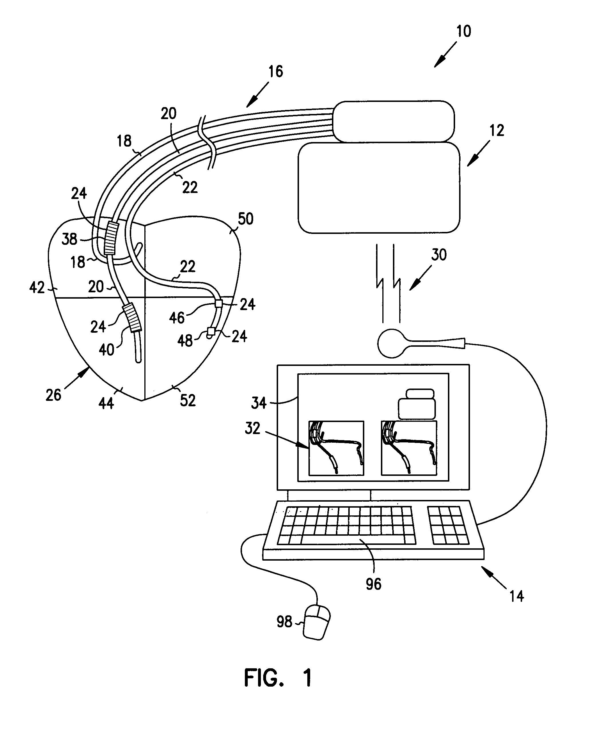
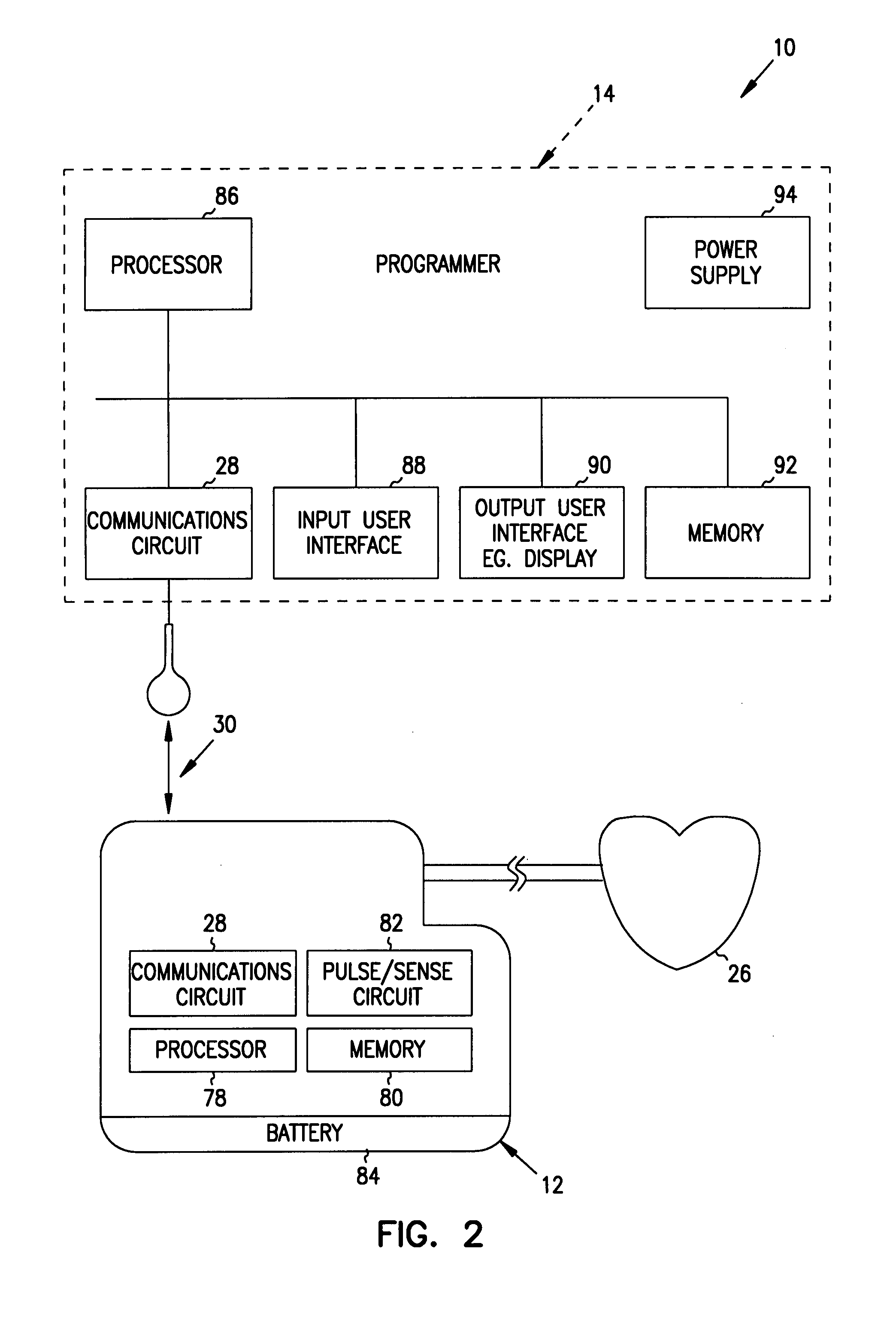
[0030]The present subject matter addresses the aforementioned problems, and aspects of the present subject matter are shown and described herein. The present subject matter provides an interface for graphically displaying the configuration of medical devices. One embodiment graphically represents, illustrates or displays the lead(s), the electrode(s), the pulse polarity, and the electrical vectors associated with the configuration.

[0031]Various aspects of t...


PUM


Abstract

Systems and methods are provided for graphically configuring leads for a medical device. According to one aspect, the system generally comprises a medical device and a processing device, such as a programmer or computer, adapted to be in communication with the medical device. The medical device has at least one lead with at least one electrode in a configuration that can be changed using the processing device. The processing device provides a graphical display of the configuration. In one embodiment, the graphical display graphically represents, illustrates or displays the lead(s), the electrode(s), a pulse polarity, and a vector. According to another aspect, the method generally comprises receiving information for a medical device having at least one lead with at least one electrode in a configuration, and presenting a graphical representation of the configuration on a display. According to other aspects, a device and a computer-readable medium encoded with a software program for providing a graphical display of a lead configuration for an implantable medical device are also provided herein.

Description

FIELD OF THE INVENTION[0001]This invention relates generally to the field of medical devices, and more particularly to systems and methods for graphically representing configurations for medical devices.BACKGROUND[0002]Medical devices, including cardiac stimulus devices such as implantable cardiac pacemakers and implantable cardioverter defibrillators (ICDs), are surgically implanted within a patient and have one or more electrical leads that conduct signals to and receive signals from the patient's heart. Each electrical lead has at least one electrode. Electrode types include ring, tip, and coil electrodes. Tip electrodes are positioned at the tip of the lead, and ring electrodes are bands positioned along the length of the lead. Coil electrodes are exposed conductor coils positioned along the lead, and are often used as part of a defibrillator to disperse a strong signal throughout the heart. Several of these electrode types may be placed on a single lead, and several of these le...

Claims


Application Information

Patent Timeline
IPC IPC(8): A61N1/00A61B5/04A61N1/372
CPCA61N1/368A61N1/37247A61N1/3962A61N1/3993A61N1/37264A61N1/0563A61N1/3684Y10S128/92Y10S128/922Y10S128/923A61N2001/0585A61N1/39622
Inventor LINDH, PARKALGREN, JAMESWENTKOWSKI, RENE H.LOCKHART, JOHN
Owner CARDIAC PACEMAKERS INC
Why Eureka
Try Eureka