Butt plate for feller buncher

a buncher and butt plate technology, applied in the field of butt plate for a buncher, can solve the problems of limiting the size and number of trees which can be accumulated, difficult construction, and only allowing the rearward push of the tree, so as to prevent the deflection of the saw blade

Active Publication Date: 2007-07-03
DEERE & CO
View PDF24 Cites 8 Cited by
  • Summary
  • Abstract
  • Description
  • Claims
  • Application Information

AI Technical Summary

Benefits of technology

[0012]In another aspect of the invention, a felling head for a feller buncher is provided. The felling head includes a saw housing securable to a logging vehicle, a disc saw blade mounted in the saw housing and having an exposed front portion in a severance area of the housing, and a motor, centered in the saw housing for turning the disc saw blade. A butt plate mounted in the saw housing over the disc saw blade is generally parallel to the blade, and includes a portion that is angled upward from the severance area to an outer edge of the butt plate to form a sloping accumulation pocket for supporting accumulated trees from an outer edge of a butt end of each tree supported on the sloping accumulation pocket. The butt plate can include a debris plate that is coupled beneath the downwardly sloping accumulation pocket in the portion that extends radially beyond the teeth of the saw blade at an entry of the teeth into the saw housing to limit debris from entering the saw housing. The debris plate preferably has a surface that is sloped at the same angle as the accumulation pocket, and can also include a channel over the teeth of the saw blade to provide clearance between the debris deflector and the teeth of the saw blade. A check plate can also be provided between the saw blade and the housing to prevent deflection of the saw blade that would result in teeth of the saw blade impacting the housing.
[0013]To limit the entry of debris into the saw housing, the angled portion of the butt plate can be directed along a line along the butt plate selected to direct the flow of chips and debris to exhaust the chips through the saw housing. The saw housing can also include a backplate extending vertically from a back section and opposing side sections of the accumulation pocket to provide a surface against which accumulated trees can rest.

Problems solved by technology

With this arrangement, trees can only be pushed rearwardly to a limited degree, and there is little space for tree storage, and essentially no space for a separate accumulation area, thereby limiting both the size and number of trees which can be accumulated.
While these butt plates provide a large accumulator, they are difficult to construct as they require multiple bends, machining, bolting and / or welding of the butt plate 4 and ramp 6, as shown in FIG. 3.
Accumulating trees, therefore, requires a significant degree of force and energy.
Additionally, because the accumulation area is flat, once the trees are severed and provided on the accumulation area, they are difficult to keep straight and can slide back and forth on the accumulation plate.
Bundles of accumulated trees, therefore, are not stable in the accumulator pocket and can shift during operation.

Method used


Image

  • Butt plate for feller buncher
  • Butt plate for feller buncher
  • Butt plate for feller buncher

Examples


second embodiment

[0045]Referring now to FIG. 8, a butt plate 12 constructed in accordance with the invention is shown. Here, again, the butt plate 12 comprises a first generally toroidal section 13 and an accumulation pocket 15 which includes a ramped portion 16, and is constructed generally as described above with reference to FIG. 4. Here, however, rather than extending parallel to the longitudinal center line 20 drawn in the machine direction (i.e. the direction of straight line forward travel of the machine to which the head is attached), the bend line 42 is angled across the butt plate 12, extending from a first point on the curved portion 33 of the front edge 40 of the butt plate 12 and offset from the center line 20 to a second point on the linear portion 21 of the back edge 44 of the butt plate 12, which is offset from but relatively closer to the center line 20, such that the bend line 42 angles toward the center line 20 as it moves from the front of the butt plate 12 toward the back of the...

third embodiment

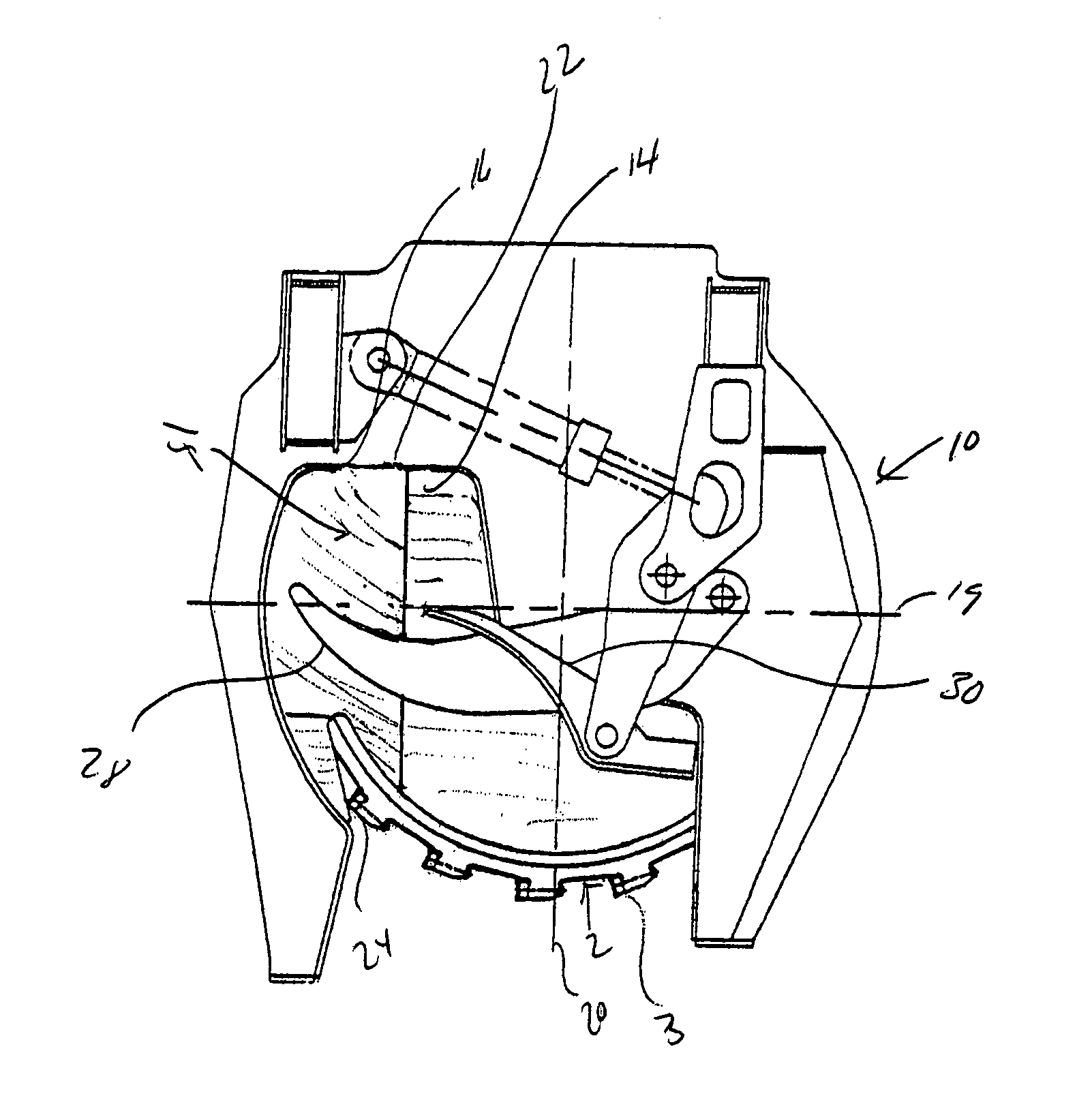
[0053]Referring now to FIG. 21, a feller head 10 including a butt plate 52 is shown. The butt plate 52 is again constructed from a flat piece of material 28 generally as described above. Here, however, the ramped portion 16 of the accumulation pocket 15 is formed with two bends 54 and 56. The bends 54 and 56 are formed in the accumulation pocket 15 along the circumference of the butt plate 12. The first bend 54 is formed extending from the exposed front at the butt plate to about the horizontal center line 19, and generally follows the curve of the outer circumference of the butt plate 12. The second bend 56 extends from the end point of the first bend, at the approximate horizontal center point 19 toward the back of the butt plate 12, again substantially following the curve of the circumference of the butt plate 12. The double bend including bends 54 and 56 therefore substantially follow the outer circumference of the butt plate from front to back.

[0054]Referring now to FIG. 22, a ...


PUM

PropertyMeasurementUnit
angleaaaaaaaaaa
angleaaaaaaaaaa
angleaaaaaaaaaa

Abstract

A butt plate for a felling head includes a ramped portion in an accumulation pocket. The ramped portion is sloped downward generally toward a line extending in the direction of forward travel of the head. The butt plate allows for high accumulation of trees while retaining stable bunches.

Description

CROSS-REFERENCE TO RELATED APPLICATION[0001]This application claims the benefit of provisional application Serial No. 60 / 467,980 filed May 5, 2003, entitled “Butt Plate for Feller Buncher”, hereby incorporated by reference.BACKGROUND OF THE INVENTION[0002]1. Field of the Invention[0003]This invention relates to forestry equipment, and in particular to a butt plate for a feller buncher for felling and accumulating trees.[0004]2. Discussion of the Prior Art[0005]Felling heads are widely used in the logging industry for accumulating several freshly cut trees in a vertical position prior to laying down the bundle at once, to be transported to roadside by a skidder or forwarder. The felling head is mounted to a heavy duty vehicle, such as a drive to tree or swing to tree wheeled or tracked vehicle, for high efficiency logging.[0006]One type of felling head uses a large saw blade disc having peripheral cutting teeth. The disc is rotated in a horizontal plane below a butt plate, with the t...

Claims


Application Information

Patent Timeline
Patent Type & Authority Patents(United States)
IPC IPC(8): A01G23/08A01G23/081
CPCA01G23/081Y10S83/928
Inventor DISABATINO, BENJAMIN
Owner DEERE & CO
Why Eureka
Try Eureka