
Fixed cutter drill bit with non-cutting erosion resistant inserts

a drilling bit and insert technology, applied in the field of drilling bits, can solve the problems of hard cutting elements degrading, drill bits that are able to economically drill through hard formations, and may have to be changed many times,

Active Publication Date: 2007-07-03
GP USA HLDG LLC
View PDF8 Cites 69 Cited by
  • Summary
  • Abstract
  • Description
  • Claims
  • Application Information

AI Technical Summary

Benefits of technology

The solution effectively reduces erosion and improves cooling of cutting elements, enhancing the drill bit's performance in challenging formations by concentrating drilling fluid flow on the cutting surfaces, thereby extending the life of the drill bits and maintaining efficiency in various drilling conditions.

Problems solved by technology

As a general rule, drill bits that are able to drill rapidly through soft formations cannot penetrate the harder formations and, similarly, drill bits that are able to drill through harder formations are not aggressive enough to economically drill through softer formations.
Thus, when drilling deep wells through many different types of rock and soil, drill bits may have to be changed many times in response to wear or in response to changing soil conditions.
However, it is also apparent from examination of used drill bits that the superhard cutting elements do degrade.
The degradation of the superhard cutting elements may be caused, at least in part, by the high temperatures generated at the cutting face from the friction of scraping rock.
However, PDC bits generally have exposed steel or infiltrated matrix surfaces adjacent to the diamond cutting elements, which can rapidly erode in the high velocity, abrasive laden stream of drilling fluid.
Unfortunately, directing the flow of drilling fluid in this manner can cause severe erosion of the surfaces adjacent to the cutting elements.
Thus, although directing the drilling fluid at the diamond cutting elements on PDC bits would provide better cooling and longer life, commercial drill bits typically do not generally incorporate this feature because of erosion.
As a consequence, typical PDC drill bits may not perform well where very high cutting element face friction is present, such as in hard rock drilling.
In addition, where soft, sticky formations are encountered, such as shales with high clay content, the hydraulic action of conventional PDC drill bits is sometimes inadequate to clean the cuttings away from the bit body and the cutting elements resulting in a phenomenon known as bit balling.
Unfortunately, welded hardmetal can crack as the blades of the PDC drill bit bend in response to the drilling loads.
Once a crack starts, the impinging drilling fluid quickly erodes the exposed, soft underlying steel.
Applying welded hardmetal is typically a hand-applied process and it is difficult to apply to the sides and bottom of the channels on the cutting face of PDC bits.
Once the welded hardmetal is applied, it is generally so thick and uneven that it affects the hydraulic flow of the flushing fluids.
The swirls and flow eddies in the wake of these thick, rough layers can make the erosion problem even worse.
Finally, the temperature caused by the welding process not only affects the heat treatment of the steel PDC bit bodies, as it can also cause the bodies to warp and even crack due to the thermal stresses.
The temperature due to welding may also have a deleterious effect on the diamonds themselves if the DDC cutting elements are brazed prior to performing the welding process.
Unfortunately, the problem with this and all other flame spray type coating processes is that the sprayed particle stream must impinge nearly perpendicular to the surface to be coated to make the coating adhere to the cutting face of the bit body.
Although sprayed coatings can provide good erosion protection on some areas of the drill bit, the coating does not adhere well to the blade surfaces that are approximately parallel to the cutting face.
Since these channels usually have vertical walls, spray type coatings do not provide adequate erosion resistance in these areas of the drill bit.
These limitations greatly reduce the effectiveness of the flame spray processes for producing wear and erosion resistant coatings on PDC bits.
Unfortunately, infiltrated or matrix bits are expensive to manufacture.
Each bit must be cast in a mold in a very labor intensive process.
Infiltrated or matrix bit bodies are also weak in bending, so the blade height achievable with an infiltrated product is limited by the intrinsic strength of the material in bending.
As a result, matrix drill bits do not provide the very high (and desirable) rates of penetration of PDC bits.
Finally, because the matrix drill bit products use a relatively soft copper based infiltrate to bind the tungsten carbide together, the infiltrated drill bit product can also be subject to erosion as the fluid stream attacks the copper binder, weakening the matrix and allowing tungsten carbide to be loosened from the body.
The matrix design provides some erosion improvement over steel, but is still subject to all the limitations described above.
Although PDC type drill bits are shown and described in these patents, it is impractical to clad the vertical surfaces as shown.
This is because the movement of the pressure transfer media tends to scrape the powders from the vertical steel surface as the press closes.
Also, because the steel body itself is incompressible, the pressure transfer media will not be able to move in a manner which allows for an even pressure distribution.
The end product of the above described cladding process has many of the same deficiencies as the flame spray coatings previously described, in that the vertical surfaces will not have adequate erosion protection.

Method used


Image

  • Fixed cutter drill bit with non-cutting erosion resistant inserts
  • Fixed cutter drill bit with non-cutting erosion resistant inserts
  • Fixed cutter drill bit with non-cutting erosion resistant inserts

Examples


Embodiment Construction

[0033]Illustrative embodiments of the invention are described below. In the interest of clarity, not all features of an actual implementation are described in this specification. It will of course be appreciated that in the development of any such actual embodiment, numerous implementation-specific decisions must be made to achieve the developers' specific goals, such as compliance with system-related and business-related constraints, which will vary from one implementation to another. Moreover, it will be appreciated that such a development effort might be complex and time-consuming, but would nevertheless be a routine undertaking for those of ordinary skill in the art having the benefit of this disclosure.

[0034]The present invention will now be described with reference to the attached figures. The words and phrases used herein should be understood and interpreted to have a meaning consistent with the understanding of those words and phrases by those skilled in the relevant art. No...


PUM

PropertyMeasurementUnit
erosionaaaaaaaaaa
distanceaaaaaaaaaa
superhardaaaaaaaaaa

Abstract

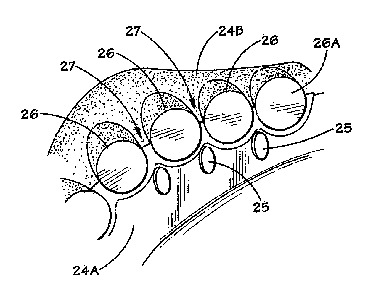
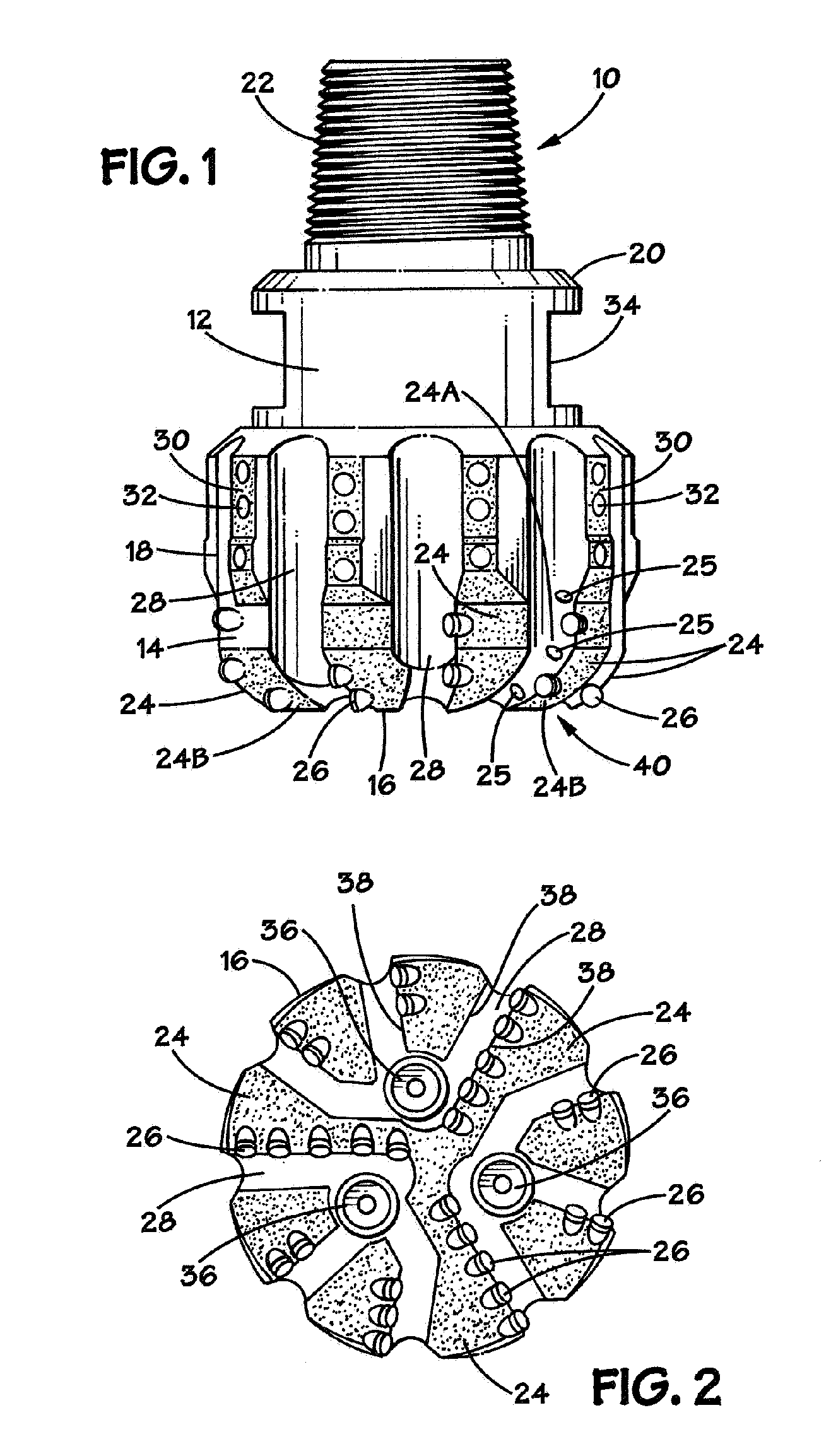
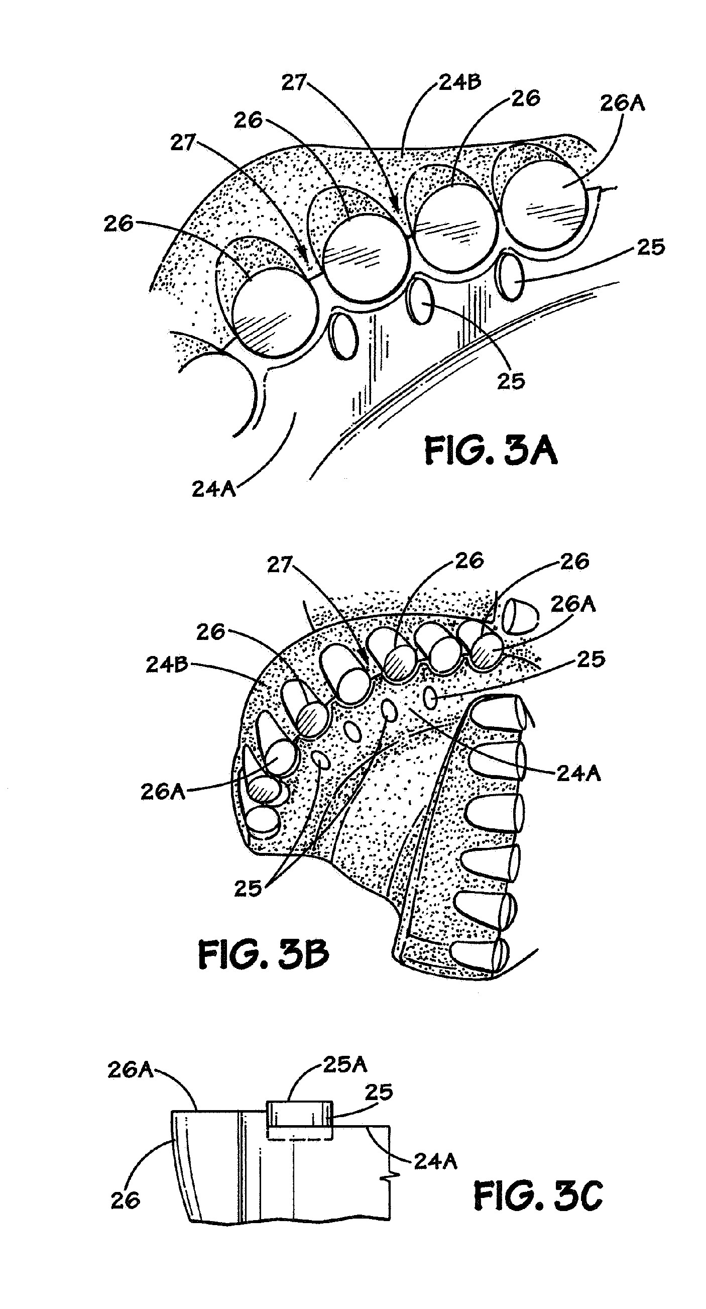
The present invention is directed to a drill bit with non-cutting erosion resistant inserts. In one illustrative embodiment, the apparatus comprises a matrix drill bit body comprising a plurality of blades, a plurality of cutting elements positioned on each of the blades, the cutting elements defining a plurality of web regions, and a plurality of spaced apart, non-cutting erosion resistant inserts positioned along a face of at least one of the blades, at least a portion of each of the non-cutting erosion resistant inserts being positioned in front of one of the web regions.

Description

BACKGROUND OF THE INVENTION[0001]1. Field of the Invention[0002]The present invention is generally related to the field of drill bits used in drilling oil and gas wells, and, more particularly, to a fixed cutter drill bit with non-cutting erosion resistant inserts.[0003]2. Description of the Related Art[0004]Oil and gas wells are formed by a rotary drilling process. To that end, a drill bit is mounted on the end of a drill string which may be very long, e.g., several thousand feet. At the surface, a rotary drive mechanism turns the drill string and the attached drill bit at the bottom of the hole. In some cases, a downhole motor may provide the desired rotation to the drill bit. During drilling operations, a drilling fluid (so-called drilling mud) is pumped through the drill string and back up-hole by pumps located on the surface. The purpose of the drilling fluid is to, among other things, remove the earthen cuttings resulting from the drilling process.[0005]There are two basic typ...

Claims


Application Information

Patent Timeline
Patent Type & Authority Patents(United States)
IPC IPC(8): E21B10/43
CPCE21B10/55Y10T408/26
Inventor DESAI, NEERALI JANUBHAISUE, JIINJEN ALBERT
Owner GP USA HLDG LLC
Learn More