
LED signal lamp

a technology of led signal lamp and led light, which is applied in the field of led signals and light emitting diodes (led) signals, can solve the problems of increasing the potential for viewing leds, and achieve the effect of reducing the footprint to generate sufficient light intensity

Active Publication Date: 2007-07-03
GE LIGHTING SOLUTIONS LLC
View PDF6 Cites 135 Cited by
  • Summary
  • Abstract
  • Description
  • Claims
  • Application Information

AI Technical Summary

Benefits of technology

[0009]As LEDs continue to improve, the footprint to generate sufficient light intensity will decrease. The present invention utilizes a novel optical element to control the light from the LEDs.

Problems solved by technology

This is undesirable.
While fewer LEDs lowers the cost of the signal, it also increases the potential for viewing the LEDs as individual point sources and for having undesirable shadows.

Method used


Image

  • LED signal lamp
  • LED signal lamp
  • LED signal lamp

Examples


Embodiment Construction

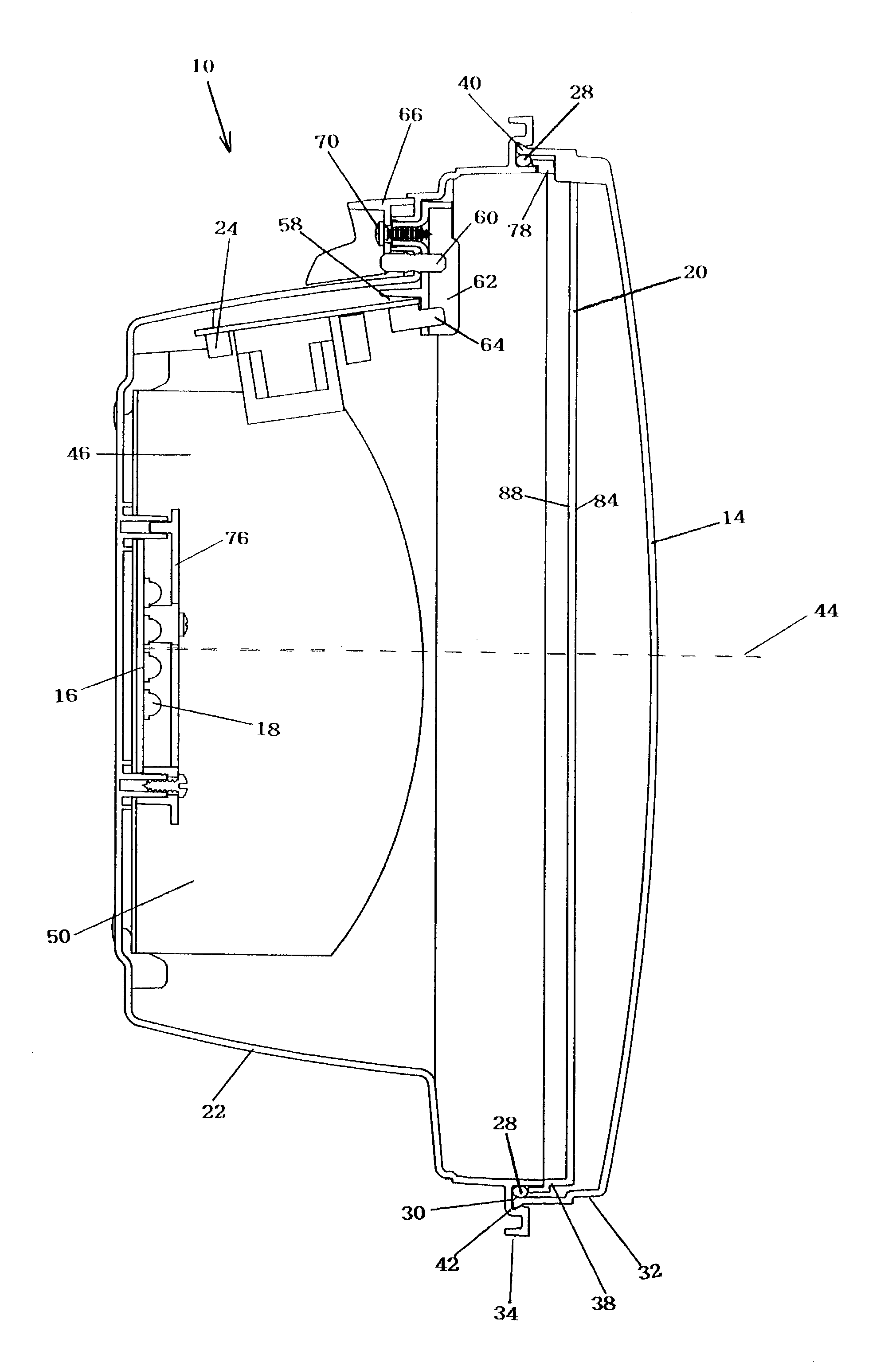
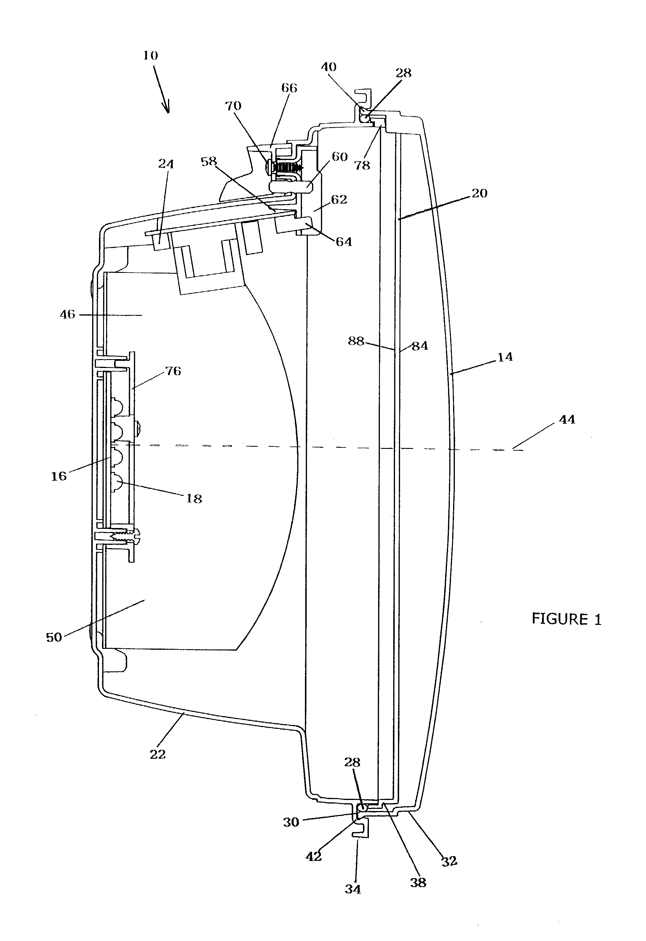
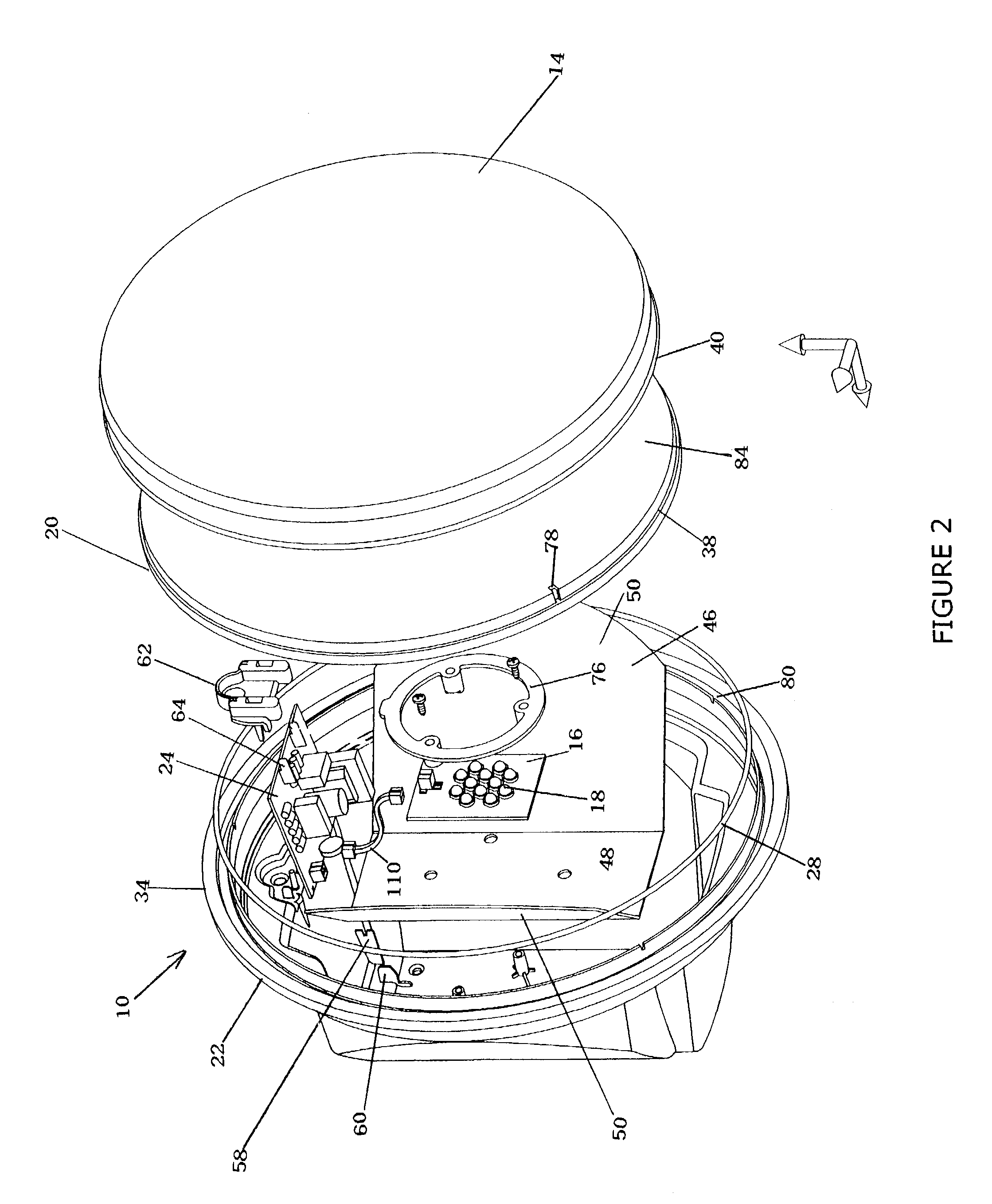
[0041]Referring to FIGS. 1 and 2, a signal lamp 10 having a housing is shown. The main components of the signal lamp 10 are shown. A housing holds the components of the signal lamp 10. The housing may be formed from, for example, polycarbonate material. Polycarbonate material has excellent strength and impact resistance characteristics. The housing is designed to be retrofit into existing incandescent traffic light signals. The housing is closed with an optically neutral cover 14.

[0042]The housing is made up of a housing base or back cover 22 and the neutral front cover 14. The front cover 14 and the base 22 mate so that the signal light is impervious to water. In one embodiment, the front cover 14 and the base 22 are snap fit together. The front cover 14 has a shoulder 30 with a lip 34. The lip 34 mates with an undercut flange 42 on the base 22. Preferably, there is an O-ring 28 between the front cover 14 and the base 22.

[0043]A dust and water-resistant seal is provided by o-ring 2...


PUM


Abstract

An LED signal using a novel optical element to control the light distribution of a small LED light source. Light emitted by the LEDs illuminates the optical element. The optical element has a plurality of clusters, shaped along the x-, y- and z-axis to control the light. After the light is distributed, it encounters a second optical surface of the optical element, typically a fresnel surface. The light is controlled by the optical element.Optionally, a lens can be placed over each LED to control the light pattern of the LED. The lens has an entry face to direct the light to a total internal reflection surface on the side, which redirects the light to the exit face. The resulting signal is a uniform, efficient signal.

Description

BACKGROUND OF THE INVENTION[0001]1. Field of the Invention[0002]The present invention relates to signals, in particular, Light Emitting Diode (LED) Signals. More specifically, the present invention relates to LED signals using a novel optical element to control the light distribution of a small LED light source.[0003]2. Description of the Related Art[0004]LED signals such as LED traffic signals, present numerous advantages over incandescent lamp traffic signals. Use of LEDs provides a power consumption savings and extremely long life compared to incandescent light sources. The long life span of the LED signals leads to improved reliability and lower maintenance costs.[0005]Due to the large number of existing incandescent traffic signals, most LED signals are designed to be retrofit into existing systems originally designed for incandescent lamps. To allow an easy retrofit without requiring significant changes to the preexisting AC power distribution and logic circuits, then LED sign...

Claims


Application Information

Patent Timeline
Patent Type & Authority Patents(United States)
IPC IPC(8): F21V5/00F21S8/00F21V5/04F21V21/02F21V21/06F21V29/00
CPCF21V5/045F21V29/20F21V31/005F21V21/02F21V21/06F21V29/004F21W2111/00F21W2111/02F21Y2101/02F21Y2115/10F21V29/70
Inventor MARTINEAU, PATRICKDUBUC, EDEN
Owner GE LIGHTING SOLUTIONS LLC
Learn More