Nut feed system and nut

a technology of nut and feed system, which is applied in the direction of threaded fasteners, instruments, manufacturing tools, etc., can solve the problems of distortion or damage to the nut bore or the cylinder, the nut bore or the cylinder may not be discovered, and the nut bore or the cylinder may not have a defect, so as to avoid distortion or damage of the nut bore or the cylinder, the effect of accurate feeding of nuts and increased cos

Inactive Publication Date: 2007-07-03
WHITESELL FORMED COMPONENTS
View PDF22 Cites 17 Cited by
  • Summary
  • Abstract
  • Description
  • Claims
  • Application Information

AI Technical Summary

Benefits of technology

[0009]Thus, a preferred embodiment of the nut feed pawl includes a central cylindrical end portion configured to be received in the counterbore and radial portions extending radially from a circumference of the central cylindrical portion, wherein the radial portions preferably have a width less than a width of the channel-shaped nut feed grooves which engage the opposed side wall of the nut feed grooves. In a preferred embodiment of the nut feed pawl, the generally cylindrical surface defines an arc of less than 180 degrees, preferably less than 150 degrees, to facilitate receipt of the cylindrical end of the nut feed pawl in the cylindrical counterbore and the nut feed grooves and prevent binding during repeated reciprocal movement of the nut feed pawl through the nut feed passage. As will be understood, the design of the nut and the nut feed pawl of this invention provides a balanced force against the nut during feeding of the nut through the nut feed passage, preventing cocking and assuring accurate feeding of the nuts through the nut feed passage without contacting the nut bore, thereby preventing distortion or damage to the nut bore while assuring feeding of the nuts through the nut passage. Further, if a nut becomes jammed in the nut passage, no damage is done to the nut bore.
[0011]The method of feeding nuts through a nut feed passage thus includes forming a nut feed groove in the end face of the nut extending generally perpendicular to an axis of the nut bore, preferably on opposed sides of the bore, forming a nut feed pawl located in the nut feed passage having an end portion configured to be received in the nut feed groove and reciprocating the nut feed pawl to feed a nut through the nut feed passage. Where the nut bore further includes a counterbore, as described above, the method of this invention includes forming and receiving a semicircular central portion at the free end of the reciprocable nut feed pawl in the counterbore and reciprocating the nut feed pawl through the nut feed passage as described above. As will now be understood, the nut feed system of this invention including the method, feed pawl and nut of this invention assures accurate feeding of nuts through the nut feed passage, avoiding jamming of the nuts in the feed passage and contact between the feed pawl and the nut bore, thereby avoiding distortion or damage of the nut bore by avoiding contact of the nut bore with the feed pawl. The nut feed grooves and counterbore in the end face of the nut may be formed during manufacture of the nut without any substantial increase in cost and the nut feed pawl may replace a conventional feed pawl without substantial modification of the feed mechanism or installation head. The method of feeding nuts through a nut feed passage of this invention further balances the force of the reciprocating nut feed pawl against the nut, particularly where the nut feed grooves are located on opposed sides of the nut bore in the end face of the nut and thus avoids cocking of the nuts in the nut passage.

Problems solved by technology

However, the nuts may encounter resistance to feeding the nuts through the nut feed passage, resulting in sufficient force applied to the nut bore or thread cylinder by the finger of the nut feed pawl to cause distortion or damage to the nut bore or thread cylinder, such that a male fastener will not thread into the nut bore.
Further, the distortion or damage to the nut bore may not be discovered until after the nut is delivered to the customer.
This is a particular problem where the nut is a self-attaching nut, such as a weld, clinch or pierce nut, where the nut is permanently installed to a panel and the defect in the nut bore or thread cylinder may not be discovered until after installation.

Method used


Image

  • Nut feed system and nut
  • Nut feed system and nut
  • Nut feed system and nut

Examples


Embodiment Construction

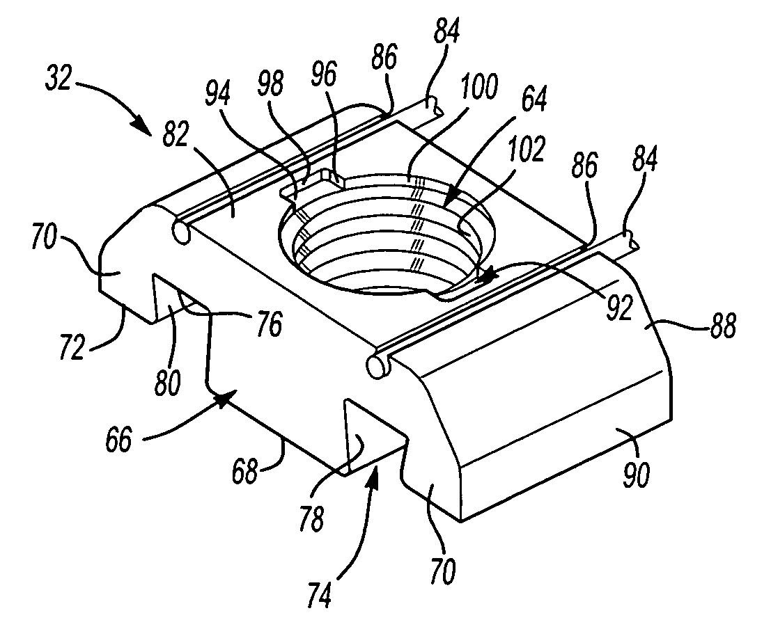
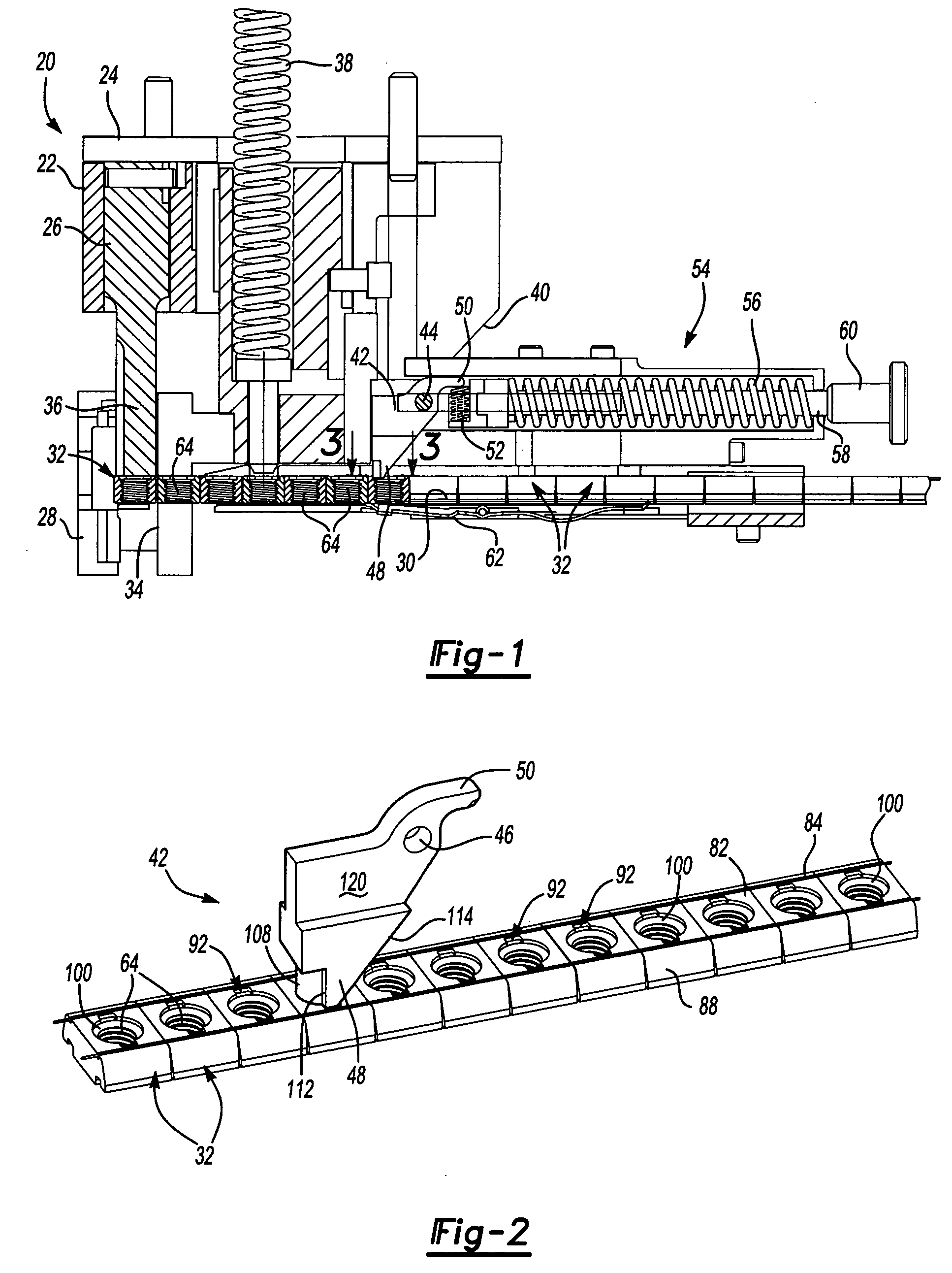
[0024]FIG. 1 illustrates a generally conventional pierce or clinch nut installation head 20. As will be understood by those skilled in this art and described further in the above-referenced U.S. patents, a pierce or clinch nut installation head is typically installed in the upper die shoe or platen of a die press (not shown), such that a pierce or clinch nut is installed in a panel with each stroke of the die press. The disclosed embodiment of the pierce or clinch nut installation head 20 includes a base member 22, which is conventionally attached to the upper die shoe or platen of a die press (not shown) having a mounting block 24 and a plunger 26 fixed relative to the base member 22. The installation head 20 further includes a nose member assembly 28 having a nut feed passage 30 receiving pierce or clinch nuts 32 and a plunger passage 34 which receives the free end 36 of the plunger 26. The installation head 20 further includes a large coil spring 38 which normally biases the nose...


PUM


Abstract

A nut feed system and method of feeding nuts through a nut feed passage which avoids contact between the feed pawl and the nut bore. The end face of the nut includes a nut feed groove extending perpendicular to the nut bore and the free end of the feed pawl is received in the groove to drive the nuts through a nut feed passage without contacting the bore. The disclosed embodiment of the nut includes a counterbore through the end face and radial channel-shaped feed grooves and the feed pawl includes a cylindrical center portion and radial portions received in the counterbore and feed grooves.

Description

FIELD OF THE INVENTION[0001]This invention relates to a nut feed system, including a method of feeding nuts, a nut feed pawl and a nut configured to receive a nut feed pawl for feeding nuts through a nut feed passage without contacting the nut bore, thereby avoiding damage of the nut bore during feeding.BACKGROUND OF THE INVENTION[0002]Nuts are typically fed through a nut feed passage by reciprocating a nut feed pawl having a finger received in the nut bore. The nut feed pawl is typically pivotally mounted on a feed mechanism, wherein the nut feed pawl is biased by a spring, pneumatic or hydraulic pressure or a positive linkage to reciprocate through the nut feed passage. The nut bore may be threaded or unthreaded to receive a thread forming or thread rolling male fastener, such as a bolt or screw. Nuts are fed through a nut feed passage for various purposes including, but not limited to, secondary operations, such as interconnecting the nuts in a strip, and installation. However, t...

Claims


Application Information

Patent Timeline
Patent Type & Authority Patents(United States)
IPC IPC(8): F16B37/04B23P19/06B65H1/08B65H5/28G07F11/00G07F11/16G07F11/68
CPCB23P19/062
Inventor VRANA, JOHN J.
Owner WHITESELL FORMED COMPONENTS
Why Eureka
Try Eureka