Fixing apparatus

a technology of fixing apparatus and fixing plate, which is applied in the direction of electric/magnetic/electromagnetic heating, instruments, electrographic processes, etc., can solve the problems of inefficient heat conduction to the roller surface, large heat loss, and the need for a long time to heat the roller surface to a sufficiently high temperature, so as to prevent leakage of magnetic flux, high heating efficiency, and stable heating. easy

Active Publication Date: 2007-07-03
KYOCERA DOCUMENT SOLUTIONS INC
View PDF25 Cites 6 Cited by
  • Summary
  • Abstract
  • Description
  • Claims
  • Application Information

AI Technical Summary

Benefits of technology

[0014]An object of the present invention is to provide a fixing apparatus of an induction heating type that efficiently heats a heating layer and that operates with reduced electric power consumption and with a short warm-up time.
[0015]Another object of the present invention is to provide a fixing apparatus that effectively prevents leakage of a magnetic flux and thereby prevents metal components located around the fixing apparatus from being heated unnecessarily.
[0016]Still another object of the present invention is to provide a fixing apparatus that, even when leakage of a magnetic flux is attempted by combining a high magnetic permeability material such as ferrite with exciting coils built into a fixing roller, can reduce the influence of heat on the high magnetic permeability material.

Problems solved by technology

This generally results in inefficient heat conduction to the roller surface and thus in a great loss of heat.
Moreover, heating the roller surface to a sufficiently high temperature requires a long time.
That is, quite inconveniently, low heat conduction efficiency results in high electric power consumption and in a long warm-up time, specifically requiring as long as several minutes for the roller surface to reach a sufficiently high temperature to achieve fixing.
This makes this fixing apparatus comparatively expensive and large.
Moreover, in the fixing apparatus described above, while the carrier member is provided with a heater, the pressure member that forms a nip between itself and the carrier member is not provided with a heater.
However, as long as paper is fed continuously, it is impossible to secure a sufficient time for their contact.
Ultimately, the pressure member may remain less hot, resulting in poorer fixing performance than is expected.
However, this construction cannot be said to achieve heating by fully exploiting the properties of a non-magnetic metal, which is inherently difficult to heat by induction heating.
This causes heat to escape from the heated part of the carrier member before it reaches the nip, and thus the energy fed from the exciting coils to the heating member is not efficiently conducted to paper.
Making an allowance for the expected drop in temperature when setting the target temperature to which to heat the carrier member leads to increased electric power consumption.
How heat is dissipated from the carrier member depends on the ambient conditions such as temperature and humidity, and therefore, if there is a long distance from the exciting coils to the nip, it makes unstable the temperature of the carrier member as it passes through the nip.
Moreover, when a heating layer made of a non-magnetic metal is heated by induction heating, the magnetic field produced by exciting coils is transmitted through the heating layer, with the result that metal components located nearby are heated unnecessarily, leading to a waste of energy and an unduly high temperature inside the apparatus.
The effect of this arrangement, however, cannot be said to be satisfactory.
Ferrite changes its properties according to temperature, and loses one of its characteristic properties, namely high magnetic permeability, at temperatures over 200° C. This may make it impossible to achieve the desired intensification of the magnetic field.

Method used


Image

  • Fixing apparatus
  • Fixing apparatus
  • Fixing apparatus

Examples


first embodiment

[0079]the invention will be described with reference to the drawings.

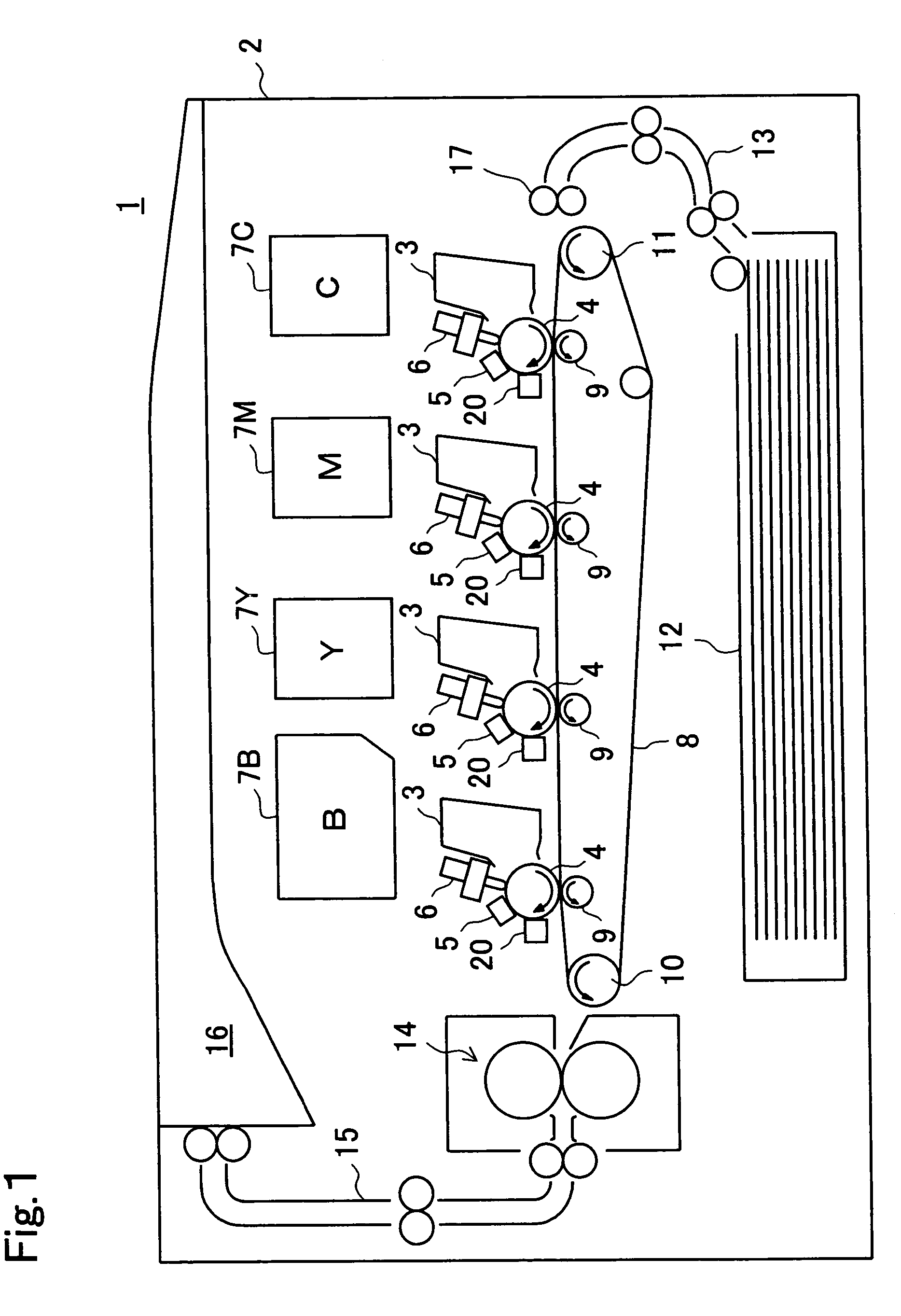
[0080]FIG. 1 shows an outline of the construction of an image forming apparatus incorporating a fixing apparatus according to the invention. A printer 1 is presented as an example of an image forming apparatus. The printer 1 incorporates, inside a body 2, developing apparatuses 3, one for each of cyan, magenta, yellow, and black colors. The developing apparatuses 3 are each provided with a photoconductive drum 4 having a photoconductive layer formed of amorphous silicon or the like. The photoconductive drum 4 rotates in the direction indicated by an arrow in the figure.

[0081]The surface of the photoconductive drum 4 is uniformly charged by a charger 5. When the charged surface of the photoconductive drum 4 is irradiated with LED light emitted from an LED print head unit 6 according to original image data fed from an external computer or the like, an electrostatic latent image is formed on the surface of the photoco...

second embodiment

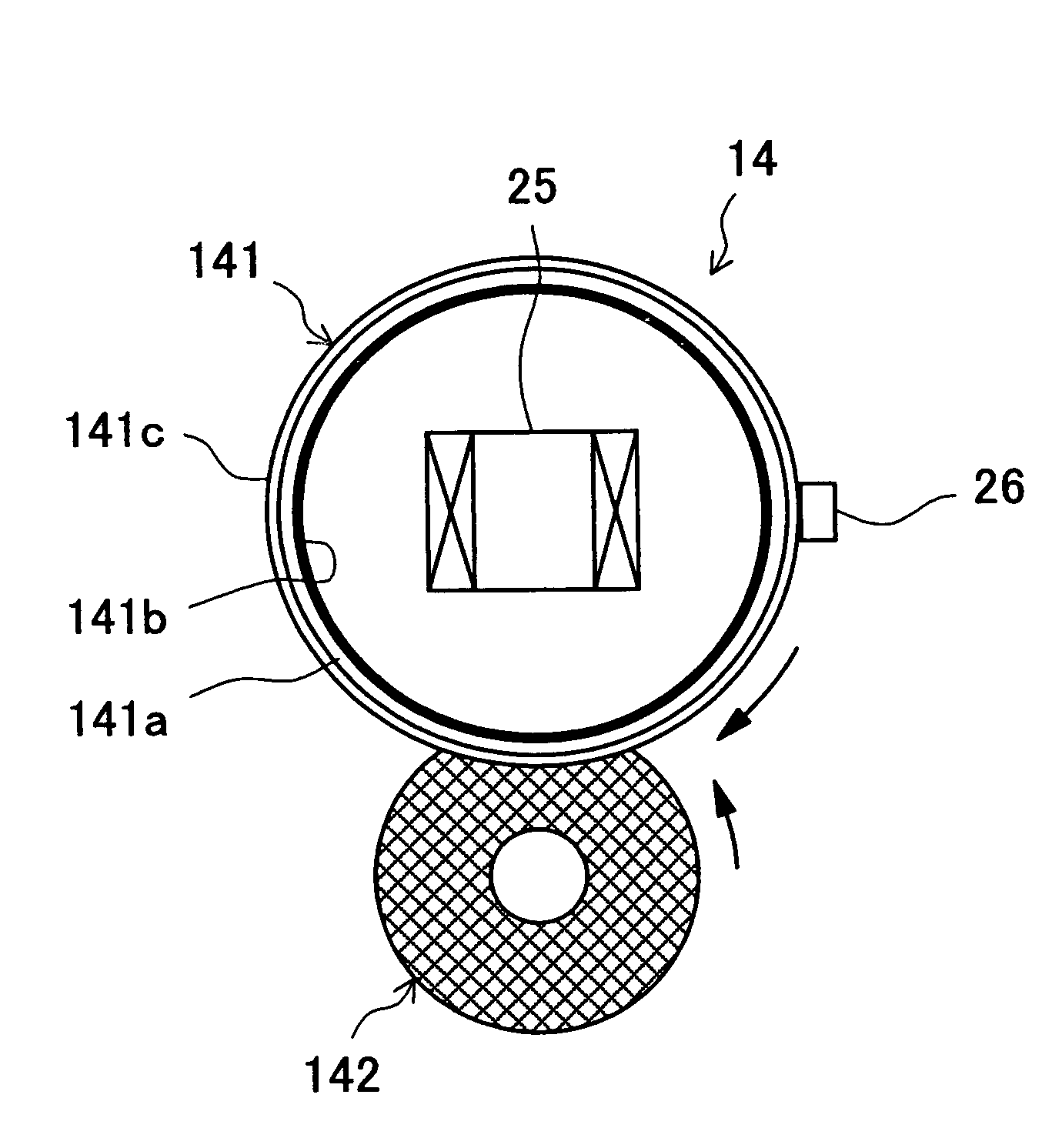
[0109]In the fixing apparatus 14 of the second embodiment, the exciting coil 25 is disposed outside the fixing roller 141 so as to face the surface of the fixing roller 141. In this case, by disposing the exciting coil 25 near the nip between the fixing and pressure rollers 141 and 142, it is possible to efficiently heat only the portion of the heating layer 141b that is nearing the nip at every moment.

[0110]By using as the thermistor 26 a non-contact-type thermistor that offers satisfactorily fast response, it is possible to eliminate friction between the stick-free layer 141c formed at the surface of the fixing roller 141 and the thermistor 26. This helps prolong the life of the fixing roller 141, in particular its stick-free layer 141c.

[0111]In a case where the exciting coil 25 is disposed outside the fixing roller 141 in this way, the heating layer 141b is formed on the outer surface of the support member 141a, and the stick-free layer 141c is formed further outside, i.e., on t...

third embodiment

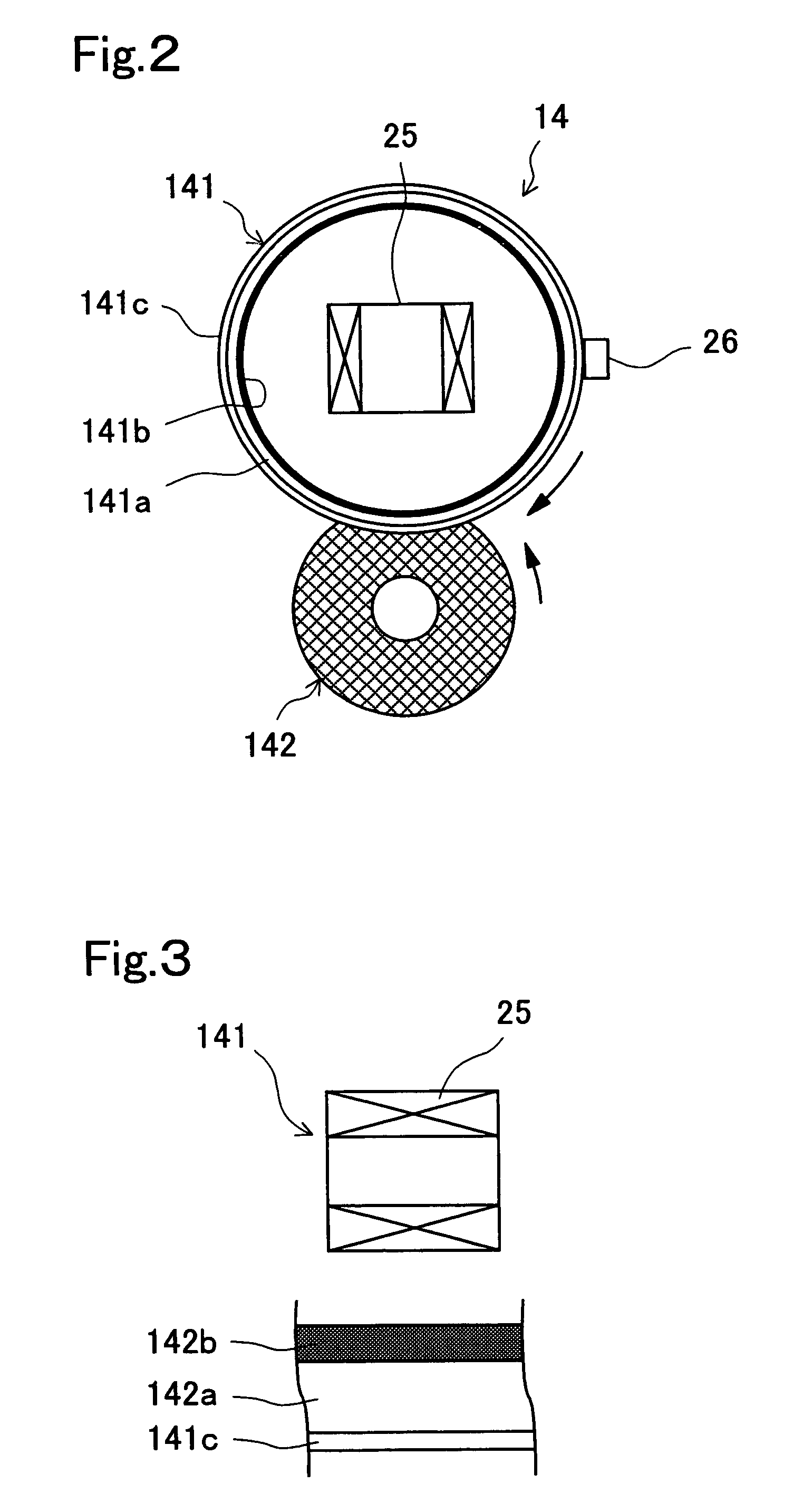
[0116]With the construction of the third embodiment, the exciting coil 25 makes also the heating layer 142b of the pressure roller 142 generate heat. Thus, paper and toner can be heated also from the side of the pressure roller 142.

[0117]Moreover, the thermistor 26 is disposed inside the fixing roller 141, and thus does not restrict the placement of the exciting coil 25. The thermistor 26 itself can be disposed in a position corresponding to the nip between the fixing and pressure rollers 141 and 142. This makes it possible to accurately measure the temperature at the nip, and thus to accurately control the temperature of the fixing roller 141 and / or pressure roller 142.

[0118]Next, the construction of the fixing apparatus of a fourth embodiment of the invention will be described with reference to FIG. 7. FIG. 7 is a sectional view showing an outline of the construction of the fixing apparatus of the fourth embodiment.

[0119]In the fixing apparatus 14 of the fourth embodiment, as in t...


PUM


Abstract

A fixing apparatus used in an image forming apparatus has a fixing member for fixing toner on paper and a pressure member making contact therewith to form in between a nip through which paper is passed. The fixing member has a support member formed of a ferromagnetic material and a heating layer formed adjacent thereto in the form of a thin layer of a non-magnetic, electrically conductive material. When a high-frequency electric current is passed through an exciting coil that is combined with the fixing member, the fixing member produces a high-frequency magnetic field, thereby produces induced eddy currents in the heating layer of the fixing member, thereby produces Joule's heat in the heating layer, and thereby heats the fixing member. A leaking magnetic flux is absorbed by the support member of the ferromagnetic member, and thus has reduced influence on metal parts located around the fixing apparatus.

Description

[0001]This nonprovisional application claims priority under 35 U.S.C. § 119(a) on Patent Application Nos. 2002-244208, 2003-053342, 2003-053368, 2002-369242, 2002-369245 filed in JAPAN on Aug. 23, 2002, Feb. 28, 2003, Feb. 28, 2003, Dec. 20, 2002, and Dec. 20, 2002, respectively which are herein incorporated by reference.BACKGROUND OF THE INVENTION[0002]1. Field of the Invention[0003]The present invention relates to a fixing apparatus for applying heat to paper carrying toner so that the toner is fused so as to be fixed on the paper. In particular, the present invention relates to a fixing apparatus that employs induction heating.[0004]2. Description of the Prior Art[0005]Heat rollers are widely used in electrophotographic image forming apparatuses. In a fixing apparatus employing a heat roller, a heat source is incorporated in at least one of a pair of rollers that forms a nip, and the pair of rollers is heated by that heat source. Paper carrying a toner image is passed through the...

Claims


Application Information

Patent Timeline
Patent Type & Authority Patents(United States)
IPC IPC(8): G03G15/20H05B6/14
CPCG03G15/2017G03G15/2053
Inventor NANJO, YUZURUNAKAJIMA, EIJIKONDO, AKIHIRO
Owner KYOCERA DOCUMENT SOLUTIONS INC
Why Eureka
Try Eureka