Dual mode outdoor vacuum

a vacuum and dual-mode technology, applied in the field of vacuums, can solve the problems of consuming and inconvenient and the use of the hose takes only a few minutes, and achieve the effects of simple, economical, and yet reliable sealing

Inactive Publication Date: 2007-07-10
ARIENS
View PDF1 Cites 3 Cited by
  • Summary
  • Abstract
  • Description
  • Claims
  • Application Information

AI Technical Summary

Benefits of technology

[0008]The hose connection between the deck and the flexible hose is mounted to and carried by the main door so that the hose connector is moved with the main door between the two operating positions, thereby simplifying and maintaining the seal between the hose connector and the suction source (i.e. impeller) when the machine is

Problems solved by technology

This design is inconvenient, first because the mounting plate must be located and then assembled to the housing for the conversion, which is time consuming and

Method used


Image

  • Dual mode outdoor vacuum
  • Dual mode outdoor vacuum
  • Dual mode outdoor vacuum

Examples


Embodiment Construction

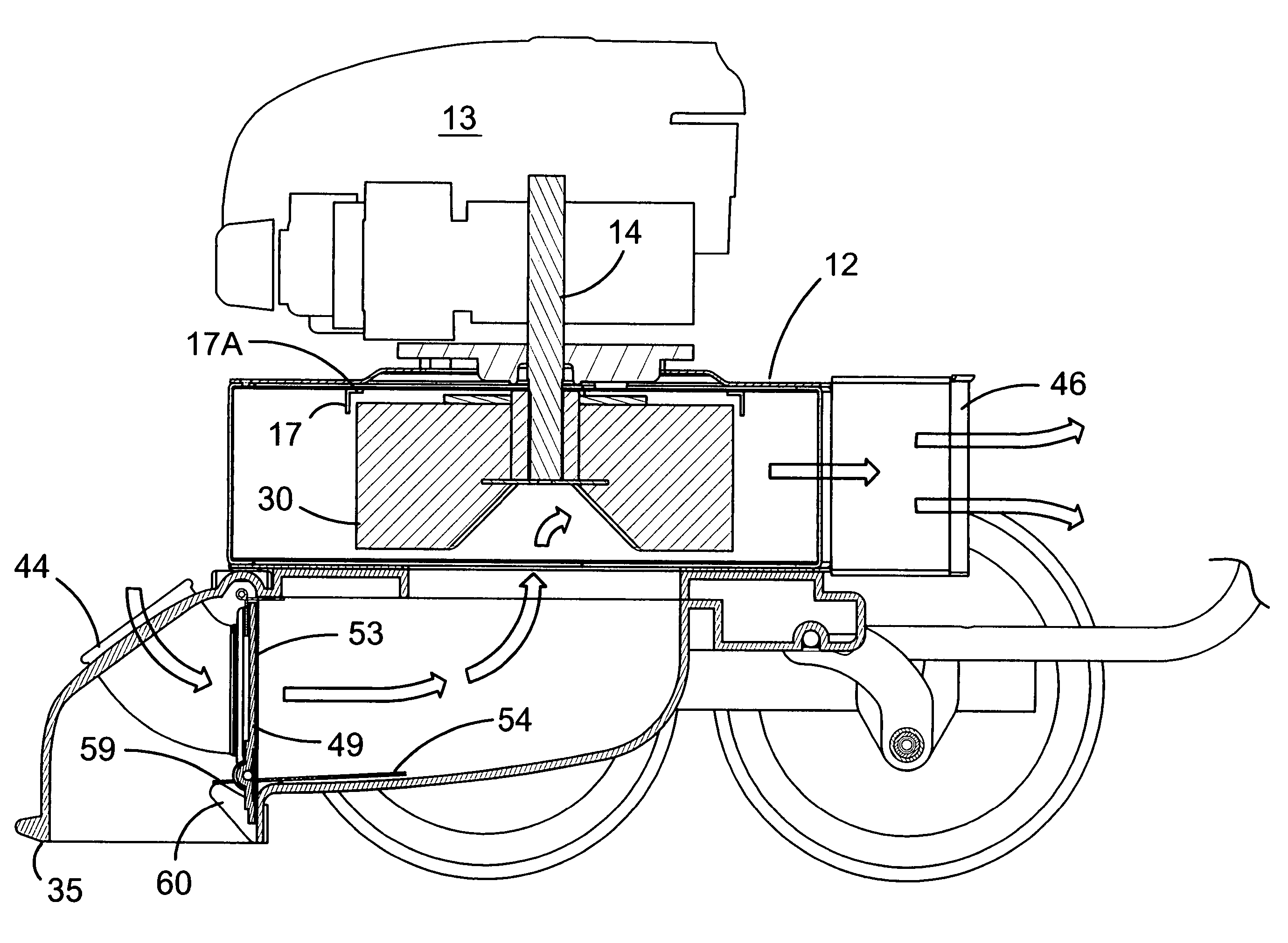
[0019]Referring first to FIG. 1, reference numeral 10 generally designates a main housing. The housing 10 includes a deck generally designated 11 on top of which an impeller housing 12 is secured by bolts or the like. On top of the impeller housing 12 is mounted a conventional gasoline engine 13 including an output shaft 14 (FIGS. 4 and 7) which extends into the impeller housing 12.

[0020]The main housing 10 is provided with four ground support wheels, the two on the left side being shown in FIG. 1 and designated 15 and 16.

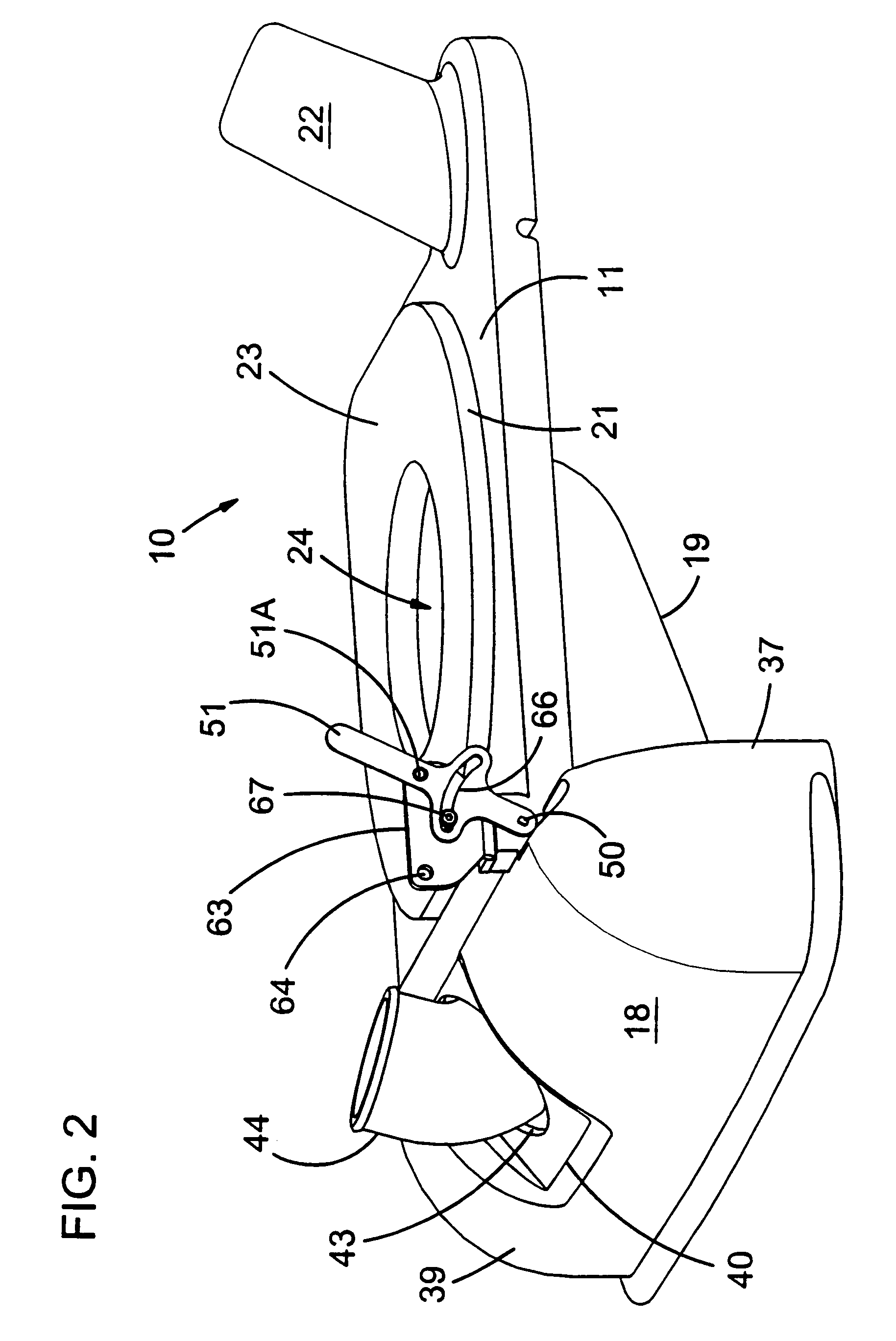
[0021]Turning now to FIGS. 2 and 8, the deck 11 is shown in more detail as including a forward section referred to as a “snout” and designated 18. A plenum 19 is formed beneath the deck 11 and to the rear of the snout 18. The snout 18, plenum 19 and deck 11 may all be molded as an integral unit.

[0022]Turning now to FIGS. 2 and 3, the deck 11 includes a platform or top wall 21 with a raised annular mounting surface 23 on which the impeller housing 12 is bolted. The ...


PUM


Abstract

A motor-driven outdoor vacuum has a ground level intake and a hose intake. When a hand-operable actuator moves a first or main door into a ground pick-up position, the ground level intake, which is carried by the first door is in direct air-flow communication with the impeller and the hose intake, which is carried by the first door is closed by a spring-actuated second door carried by the main door. When the actuator is moved to a hose intake position, the main door is moved to a second position in which the hose is in air-flow communication with the impeller and the ground level intake is closed.

Description

RELATED APPLICATION[0001]This application claims priority of co-owned U.S. provisional application Ser. No. 60 / 423,908 filed Nov. 14, 2002.FIELD OF THE INVENTION[0002]The present invention relates to vacuums of the type used for commercial, industrial, and residential outdoor applications. Vacuums of this type typically have two different operating modes. A first operating mode (the “ground pick-up” mode) has a ground-level intake in an open or active mode so that debris on a surface such as a floor, concrete slab or parking lot, or clippings on a lawn or garden area may be suctioned up and routed to a collection container. In a second mode of operation, the “hose intake” mode, a hose intake is in direct air-flow communication with a driven impeller which creates the suction, and the ground level intake is closed. In the hose intake mode, a flexible hose may be used to clean areas which are not conveniently accessible by the ground level intake, and dust and debris are routed to the...

Claims


Application Information

Patent Timeline
IPC IPC(8): A47L5/00A47L5/32E01H1/08
CPCA47L5/32E01H1/0827
Inventor CLARKE, PATRICK J.MONDIGO, JESSE V.
Owner ARIENS
Why Eureka
Try Eureka