Flexible resheathable stent design

a flexible, stent technology, applied in the field of stents, can solve the problems of human anatomy tortuous, recapturable stents subject to significant bending and flexing, and conventional recapturable stents have practical limits to the allowed amount of bending

Inactive Publication Date: 2007-07-10
MEDTRONIC VASCULAR INC
View PDF15 Cites 60 Cited by
  • Summary
  • Abstract
  • Description
  • Claims
  • Application Information

AI Technical Summary

Benefits of technology

[0008]Generally, each capture segment of the stent captures the immediately adjacent distal capture segment in a fish scale effect when the stent is in the radially compressed state.
[0009]Since each capture segment of the stent captures the immediately adjacent distal capture segment, the stent does not have loose ends or other protrusions which might catch on the end of a sheath as the sheath is slid from a proximal end to a distal end of the stent. By forming the stent with an absence of any loose ends or other protrusions which can be caught by the end of the sheath, a partially retracted sheath can be advanced distally back over the exposed portion of the stent thus recapturing the stent.
[0011]Since the stent is relatively flexible, the stent can be significantly bent and flexed during guidance to the desired location thus maximizing the range of anatomical variation in which the stent can be used. Further, since the stent is relatively conformal, the stent conforms to a wide range of vessels thus further maximizing the range of anatomical variation in which the stent can be used.

Problems solved by technology

However, the human anatomy is tortuous by nature.
Thus, during guidance of the recapturable stent to the desired location, the recapturable stent is subjected to significant bending and flexing.
A conventional recapturable stent has practical limits to the allowed amount of bending.
Avoiding extreme bending of the recapturable stent limits the range of anatomical variation in which the recapturable stent can be used.
Additionally, a conventional recapturable stent is relatively non-conformal thus further limiting the range of anatomical variation in which the recapturable stent can be used.

Method used


Image

  • Flexible resheathable stent design
  • Flexible resheathable stent design
  • Flexible resheathable stent design

Examples


Embodiment Construction

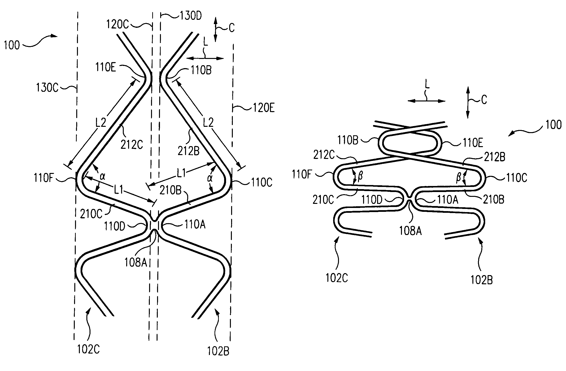
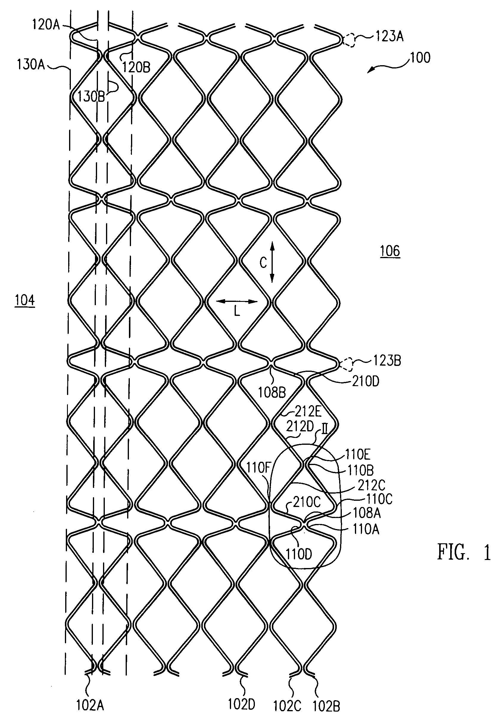
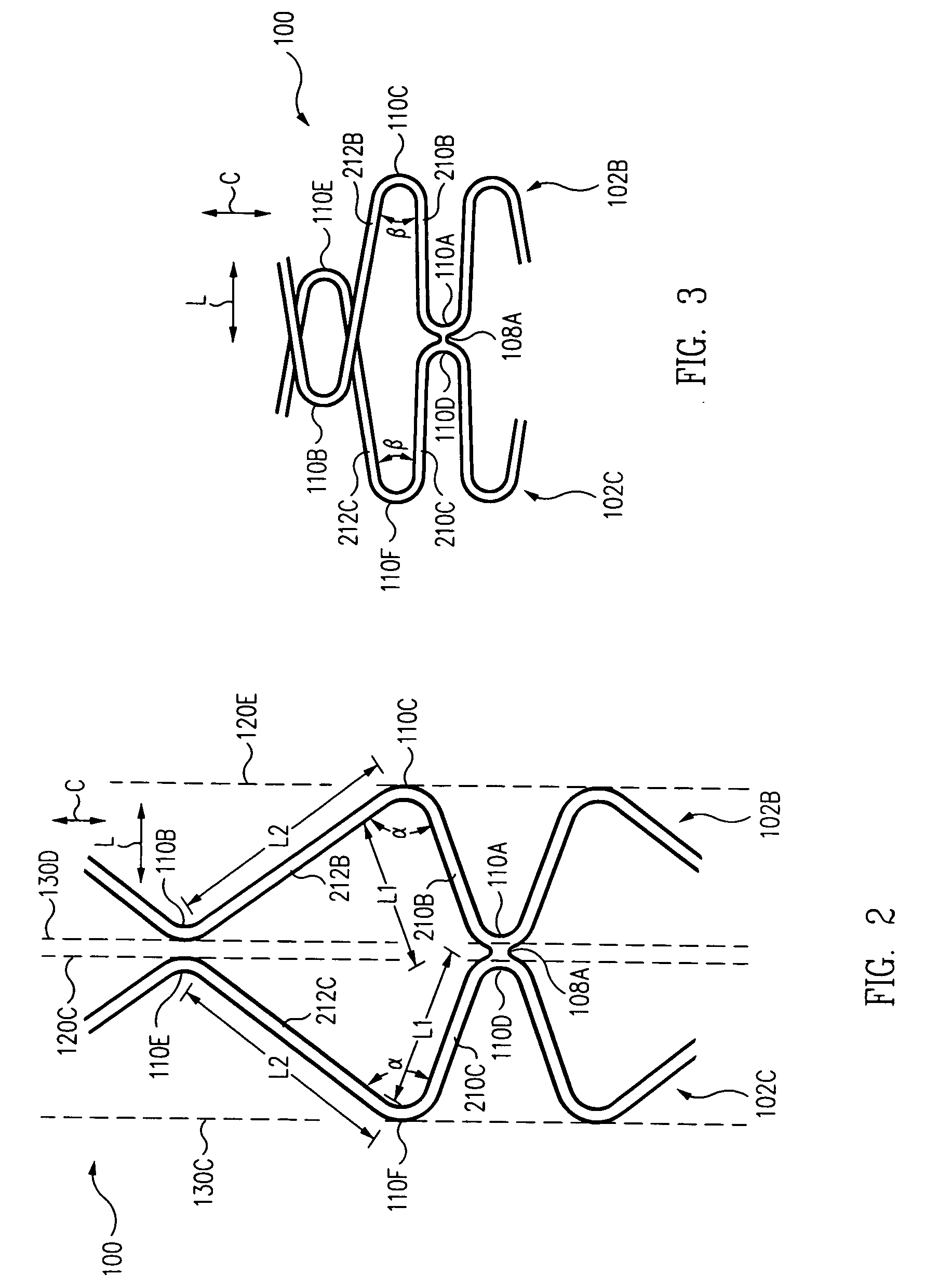
[0027]FIG. 1 is a laid flat approximately half circumference plan view of a self-expanding stent 100 in an expanded configuration in one embodiment according to the present invention. Stent 100 includes a plurality of segments, sometimes called capture segments, including capture segments 102A, B, C, D, coupled to one another. Although eight capture segments are illustrated in FIG. 1, stent 100 can be formed with more or less than eight capture segments 102.

[0028]Illustratively, stent 100 is integral, i.e., is a single piece and not a plurality of separate pieces connected together. For example, stent 100 is formed by laser cutting a tubular piece of material. However, in an example, capture segments could be separate pieces, which are connected together, e.g., by welding.

[0029]Stent 100 includes a distal, e.g., first, end 104 and a proximal, e.g., second, end 106. Stent 100 extends longitudinally between distal end 104 and proximal end 106 along a longitudinal axis L, i.e., in the ...


PUM


Abstract

A self-expanding stent includes capture segments including a first capture segment and a second capture segment. The first capture segment includes a first crown coupled to a first crown of the second capture segment and a second crown, where the second crown is spaced apart from an adjacent second crown of the second capture segment when the self-expanding stent is in a relaxed state, and further where the second crown of the first capture segment captures the adjacent second crown of the second capture segment when the self-expanding stent is in a radially compressed state.

Description

BACKGROUND OF THE INVENTION[0001]1. Field of the Invention[0002]The present invention relates to an intra-vascular device and method. More particularly, the present invention relates to a stent for treatment of intra-vascular diseases.[0003]2. Description of the Related Art[0004]In stent deployment systems, a self-expanding stent is restrained within a sheath. After positioning of the stent at the desired location via fluoroscopic guidance, the physician retracts the sheath to deploy the stent, i.e., to expose the stent and allow it to self-expand.[0005]Recapturable stents allow the stent to be recaptured after deployment of the recapturable stent has been initiated. More particularly, if the recapturable stent jumps or is otherwise positioned incorrectly as the physician begins to retract the sheath, the physician simply reverses the direction of the sheath and advances the sheath back over the recapturable stent to recapture the stent within the sheath. After the recapturable sten...

Claims


Application Information

Patent Timeline
Patent Type & Authority Patents(United States)
IPC IPC(8): A61F2/06
CPCA61F2/91A61F2/915A61F2002/91508A61F2002/91516A61F2230/0013A61F2002/91558A61F2002/9528A61F2210/0019A61F2250/0059A61F2002/91541
Inventor PRYOR, JACK
Owner MEDTRONIC VASCULAR INC
Why Eureka
Try Eureka