Eyewash with automatic stagnant water flushing system

a technology of automatic stagnant water and flushing system, which is applied in the direction of washstands, lighting and heating apparatus, instruments, etc., can solve the problems of increased user difficulty, extended disassembly and maintenance of the device, and increased user difficulty, so as to maintain the water quality

Active Publication Date: 2007-07-10
MUELLER INT LLC
View PDF51 Cites 9 Cited by
  • Summary
  • Abstract
  • Description
  • Claims
  • Application Information

AI Technical Summary

Benefits of technology

[0006]A discharge passage branches from the flow controlled passage upstream of the eyewash station. A discharge valve is disposed along the discharge passage for selectively permitting and prohibiting the flow of pressurized water through the discharge passage. The system further includes a programmable controller for regulating the flow of pressurized water through the discharge passage by activating and deactivating the discharge valve. As a result, stagnant water can be flushed from the flow controlled passage to maintain water quality in the flow controlled passage as delivered to the eyewash station. In addition to time based flushing, embodiments of the invention can provide temperature based flushing.

Problems solved by technology

Other devices, such as sinks and drinking fountains, may appear to be used more regularly, but there are numerous instances in which such devices may go through extended periods of disuse.
A user of one of these devices may unsuspectingly be exposed to contaminated water, potentially exacerbating or causing additional problems for the user.
In addition to these hazards, stagnant water in the supply line may become excessively hot or cold depending on the environment in which the water delivery system is located.
Water at such temperature extremes can be harmful to the user, and it can be detrimental to the water delivery system itself.

Method used


Image

  • Eyewash with automatic stagnant water flushing system
  • Eyewash with automatic stagnant water flushing system
  • Eyewash with automatic stagnant water flushing system

Examples


Embodiment Construction

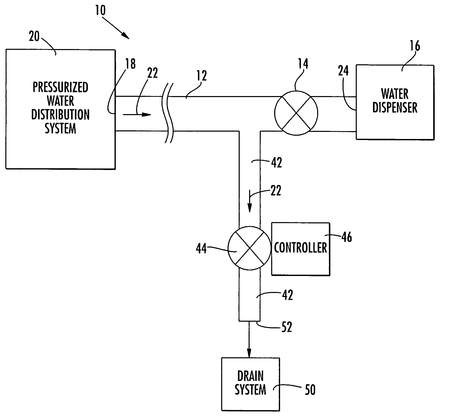
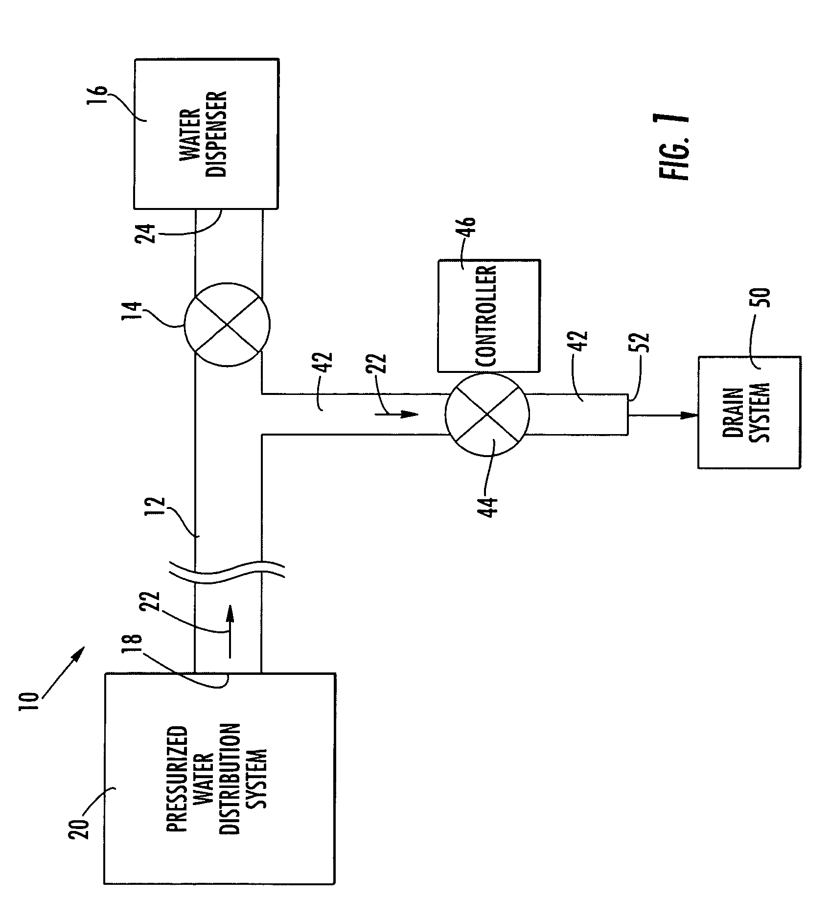
[0023]A flushing system according to aspects of the invention will be explained herein in the connection with various water delivery systems. However, it will be understood that the detailed description is intended only as exemplary. The embodiments of the invention shown in FIGS. 1–14 are not intended to limit the invention to the illustrated structure or application. One skilled in the art will readily appreciate the numerous applications in which embodiments of the invention can be employed.

[0024]Referring to FIG. 1, a water delivery system 10 can include a flow controlled passage 12, a flow control valve 14 and a water dispenser 16. Each of these components will be discussed in turn below. The flow controlled passage 12 can have an inlet 18 adapted for fluid connection to a pressurized water distribution system 20, which can be, for example, a municipal water system. The term “fluid connection,” as used herein, is intended to cover a wide range of connections, both direct and in...


PUM


Abstract

Eyewash stations can go through extended periods of disuse, allowing for the growth of bacteria and other substances in the stagnant water in the supply passages. Water dispensed from such the eyewash station can come into contact with or be consumed by a user. Embodiments of the invention provide a system that can automatically flush stagnant water from eyewash stations on a timed basis to minimize the possibility that contaminated water is delivered to a user. In addition, the automatic stagnant water flushing system according to embodiments of the invention can provide temperature-based flushing systems to avoid the dangers or discomfort associated with the delivery of excessively hot or cold water to a user.

Description

FIELD OF THE INVENTION[0001]The invention relates in general to water delivery systems and, more particularly, to a water flushing apparatus for automatically maintaining water quality in water delivery systems.BACKGROUND OF THE INVENTION[0002]Various systems are known in the art that deliver water for human use and consumption. Examples of such devices include safety showers, emergency eye wash stations, sinks, and drinking fountains. Some of these water delivery systems, by their very nature, are only contemplated as being used on an infrequent basis. For example, eye wash stations and safety showers are provided for emergency situations in which the eyes, face, skin and / or body of a person are exposed to harmful or irritable substances. Other devices, such as sinks and drinking fountains, may appear to be used more regularly, but there are numerous instances in which such devices may go through extended periods of disuse. For example, houses may have seasonal occupants, or certai...

Claims


Application Information

Patent Timeline
Patent Type & Authority Patents(United States)
IPC IPC(8): G05D23/00E03C1/00A61H33/00A61H33/04A61H35/02
CPCA61H35/02A61H33/6068A61H2033/0012A61H33/005A61H2033/0033
Inventor TAYLOR, THOMAS M.
Owner MUELLER INT LLC
Why Eureka
Try Eureka