Double-sided cutting insert and milling cutter

a technology of indexable cutting inserts and milling cutters, which is applied in the direction of shaping cutters, manufacturing tools, metal working devices, etc., can solve the problems of deficient cutting efficiency, negative axial rake angles may be disadvantageous, and the magnitude of the axial rake angle of the insert is limited

Active Publication Date: 2007-07-10
ISCAR LTD
View PDF7 Cites 111 Cited by
  • Summary
  • Abstract
  • Description
  • Claims
  • Application Information

AI Technical Summary

Problems solved by technology

However, negative axial rake angles may be disadvantageous, e.g., they have been found to be deficient in cutting efficiency for applications involving difficult to machine materials.
It will be appreciated that the magnitude of the insert axial rake angle is limited for practical reasons.
Any increase in the insert axial rake angle will result in an increase in the “vertical” extent of the increasing incident angle surface (see FIG. 3 of U.S. Pat. No. 5,333,972) that may have an adverse effect on chip development and evacuation.
Moreover, the axial rake and relief angles are interdependent and any change in the axial relief angle results in a corresponding change in the relief angle, which is not always desirable.
However, the cutting edges of such inserts may be weaker than those of negative inserts since the cutting wedge angles of double positive inserts are smaller than those of negative inserts.
Although it is conceivable to obtain double-sided reversed-relief inserts by grinding primary relief adjacent the cutting edges at both ends of a negative insert, grinding is an additional manufacturing operation that increases time and production costs of the cutting inserts.

Method used


Image

  • Double-sided cutting insert and milling cutter
  • Double-sided cutting insert and milling cutter
  • Double-sided cutting insert and milling cutter

Examples


Embodiment Construction

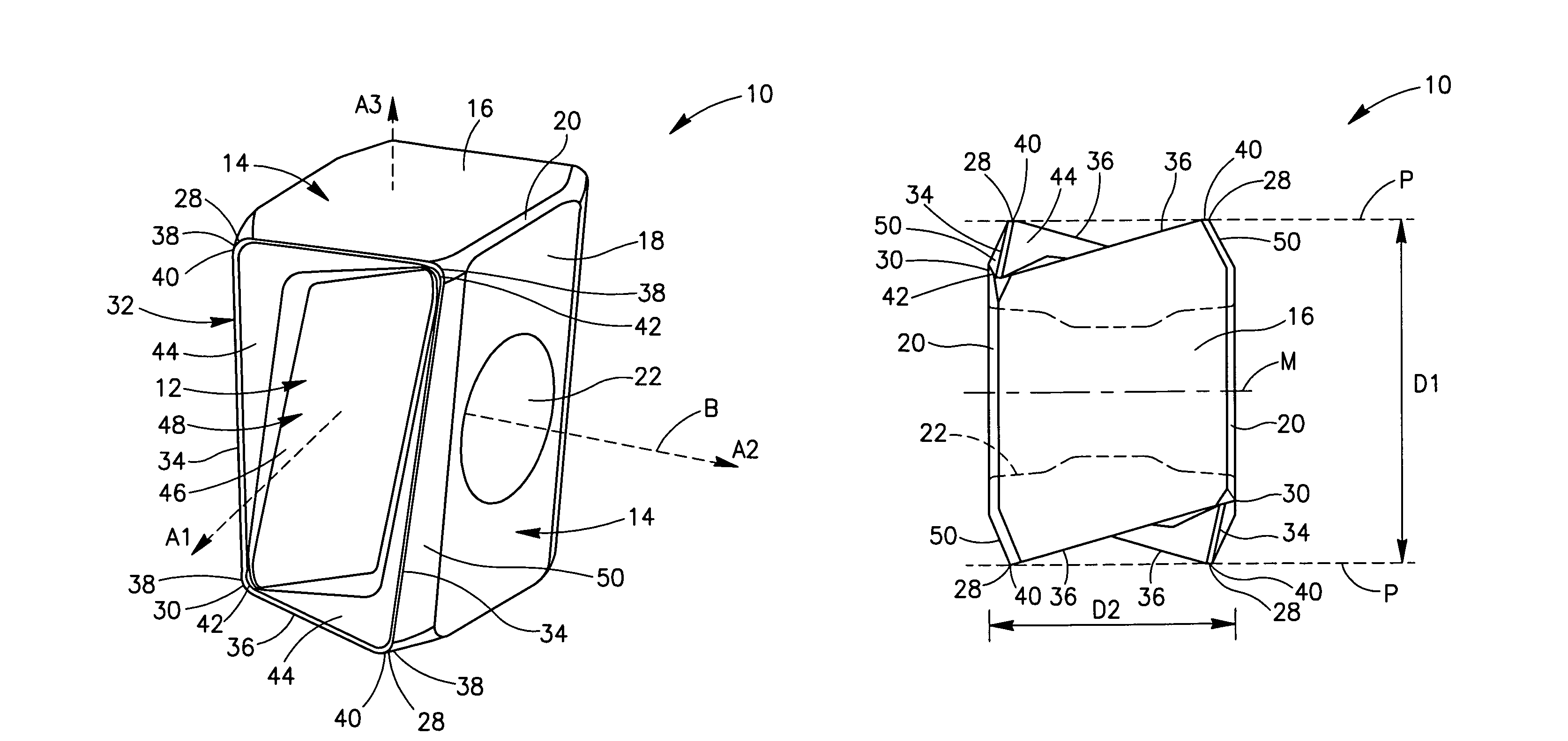
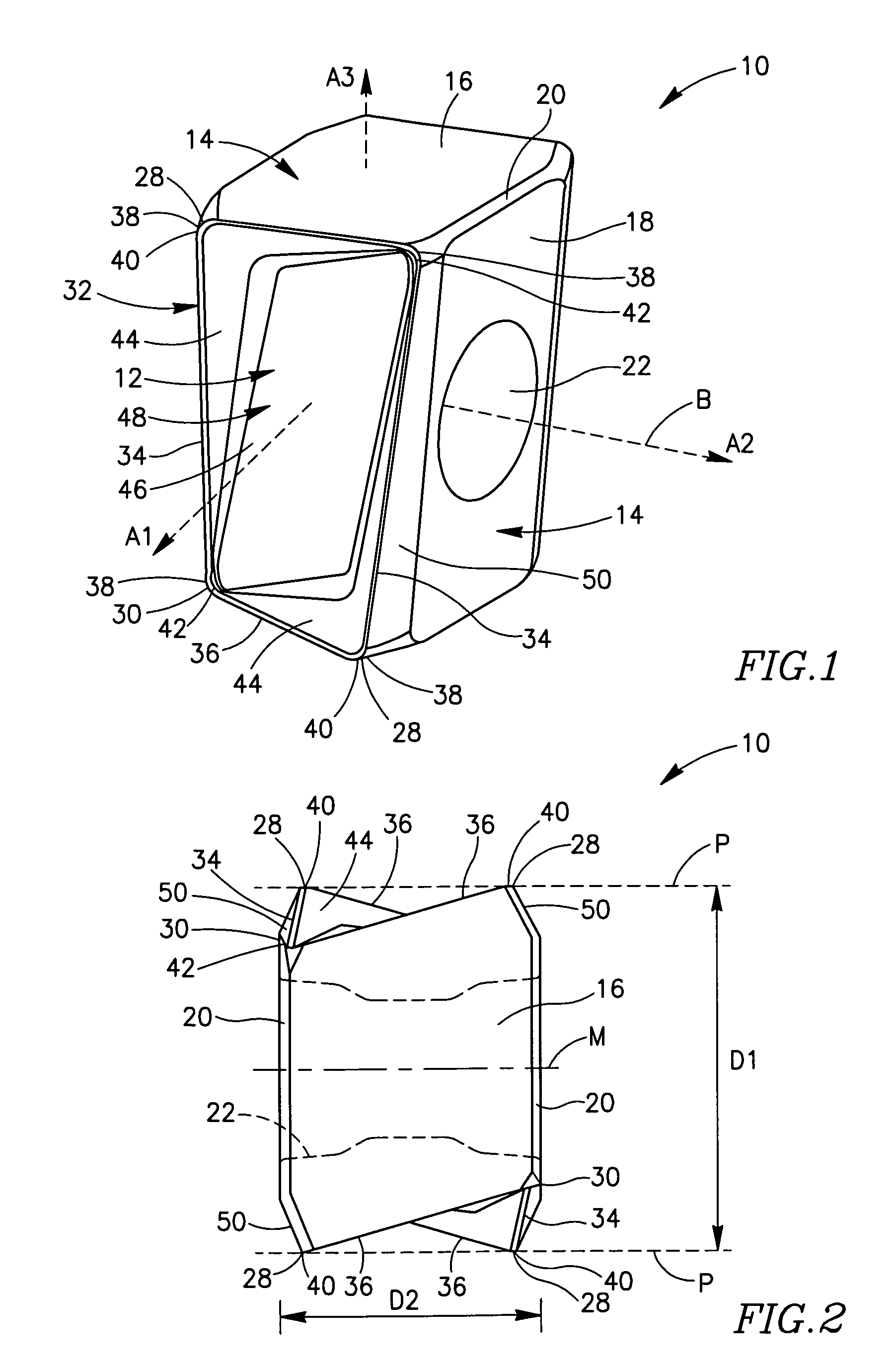
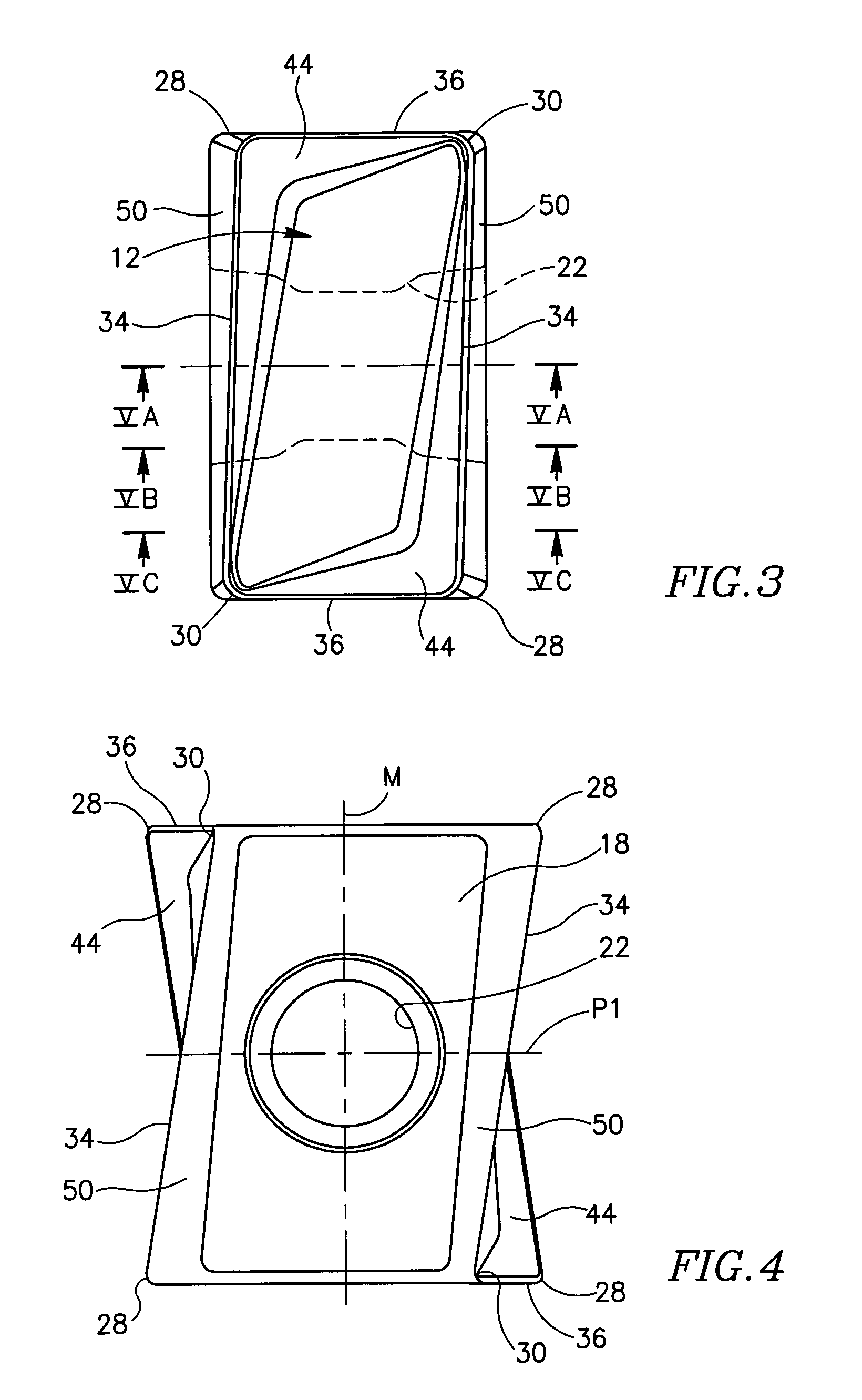
[0038]Attention is first drawn to FIGS. 1 to 7, showing a cutting insert 10 in accordance with the present invention there. The cutting insert 10 is indexable, and is typically manufactured by form-pressing or by injection molding and sintering carbide powders. The cutting insert 10 comprises two identical opposing end surfaces 12 of a generally rectangular shape in an end view of the cutting insert 10. Each end surface 12 has 180° rotational symmetry about a first axis A1 passing through the two end surfaces 12.

[0039]A peripheral side surface 14 extends between the two opposing end surfaces 12 and comprises two opposed identical minor side surfaces 16, two opposed identical major side surfaces 18 of a generally parallelogrammatic shape, and corner side surfaces 20 located between adjacent minor and major side surfaces 16, 18. The two identical opposing major side surfaces 18 each have 180° rotational symmetry about a second axis A2 which is perpendicular to the first axis A1 and pa...


PUM

PropertyMeasurementUnit
angleaaaaaaaaaa
interior angleaaaaaaaaaa
shapeaaaaaaaaaa

Abstract

A double-sided cutting insert, for use in a milling cutter, having two identical opposing end surfaces and two opposing identical major side surfaces with a through bore extending between, and opening out to, the major side surfaces. Major cutting edges are formed at the intersection of each major side surface with each end surface. Adjacent each major cutting edge, in each major side surface, is a primary relief surface. In each cross section of the cutting insert taken in a plane generally perpendicular to the major side surfaces, a line tangent to the primary relief surface at the major cutting edge is inclined to a median plane of the cutting insert at an acute interior angle.

Description

FIELD OF THE INVENTION[0001]The present invention relates to a double-sided indexable cutting insert and a milling cutter for use in metal cutting processes.BACKGROUND OF THE INVENTION[0002]There is disclosed in WO 97 / 17157 a face milling cutter employing a double-sided indexable cutting insert having a prismoidal shape with two opposed generally rectangular rake surfaces connected by side surfaces. The cutting insert has a basic “negative” geometry and therefore in order to provide the necessary clearance between the cutting insert and the workpiece, when mounted in a face-mill, the cutting insert is oriented with a negative axial rake angle. However, negative axial rake angles may be disadvantageous, e.g., they have been found to be deficient in cutting efficiency for applications involving difficult to machine materials.[0003]A double-sided indexable cutting insert for a boring tool head is disclosed in U.S. Pat. No. 5,333,972. The insert is provided at each end with a protruding...

Claims


Application Information

Patent Timeline
Patent Type & Authority Patents(United States)
IPC IPC(8): B23C5/00B23C1/00B23C5/22
CPCB23C5/2221B23C2200/0433B23C2200/085B23C2200/125B23C2200/286Y10T407/24B23C2200/367Y10T407/245Y10T407/23Y10T407/235B23C2200/361B23C5/2213B23C2200/284
Inventor SMILOVICI, CAROLBALLAS, ASSAF
Owner ISCAR LTD
Why Eureka
Try Eureka