Center touch method and apparatus for forming contact lenses

a touch-based, contact lens technology, applied in the field of contact lenses, can solve the problems of reducing production yields and driving up costs, discomfort to wearers, and/or not accurately correcting wearers' vision, so as to prevent mis-shaped lenses and adequately correct wearers' vision

Inactive Publication Date: 2007-07-10
JOHNSON & JOHNSON VISION CARE INC
View PDF13 Cites 4 Cited by
  • Summary
  • Abstract
  • Description
  • Claims
  • Application Information

AI Technical Summary

Benefits of technology

[0014]By engaging a central portion of the back curve mold half, the center touch engaging method and apparatus of the present invention are able to close the contact lens mold assembly precisely by guiding the back curve mold half into engagement with the front curve mold half. In addition, supporting the central portion of the back curve mold half prevents flexing of the portion of the back curve mold half which corresponds to the optical zones of the resultant lenses and allows excess liquid contact lens material to be expelled, thereby preventing misshaped lenses. Accordingly, the method and apparatus of the present invention enable a contact lens to be produced which is well shaped with minimal decentration, thereby producing a comfortable lens for the wearer which can adequately correct the wearer's vision.
[0015]It follows from the foregoing that an objective of the present invention is to enable precise closure of a contact lens mold assembly comprising a front curve mold half and a back curve mold half.
[0017]Yet another objective of the present invention is to prevent flexing of a portion of the back curve mold half corresponding to an optical zone of a resultant contact lens during the closing of a contact lens mold assembly.

Problems solved by technology

If the mold halves are not mated precisely, lens abnormalities may result which could cause discomfort to the wearer and / or not accurately correct the wearer's vision.
If the decentration and thicknesses are unacceptable, the lenses are discarded, thereby reducing production yields and driving up costs.
In contact lenses with decentration, the edges of the contact lenses may be uneven, causing discomfort to the wearer.
In addition, improper thicknesses may affect the ability of the contact lenses to adequately correct a wearer's vision.
Improper closure may result in decentric lenses which produce discomfort to the wearer and misshaped lenses that reduce the subjective comfort of the wearer.

Method used


Image

  • Center touch method and apparatus for forming contact lenses
  • Center touch method and apparatus for forming contact lenses
  • Center touch method and apparatus for forming contact lenses

Examples


Embodiment Construction

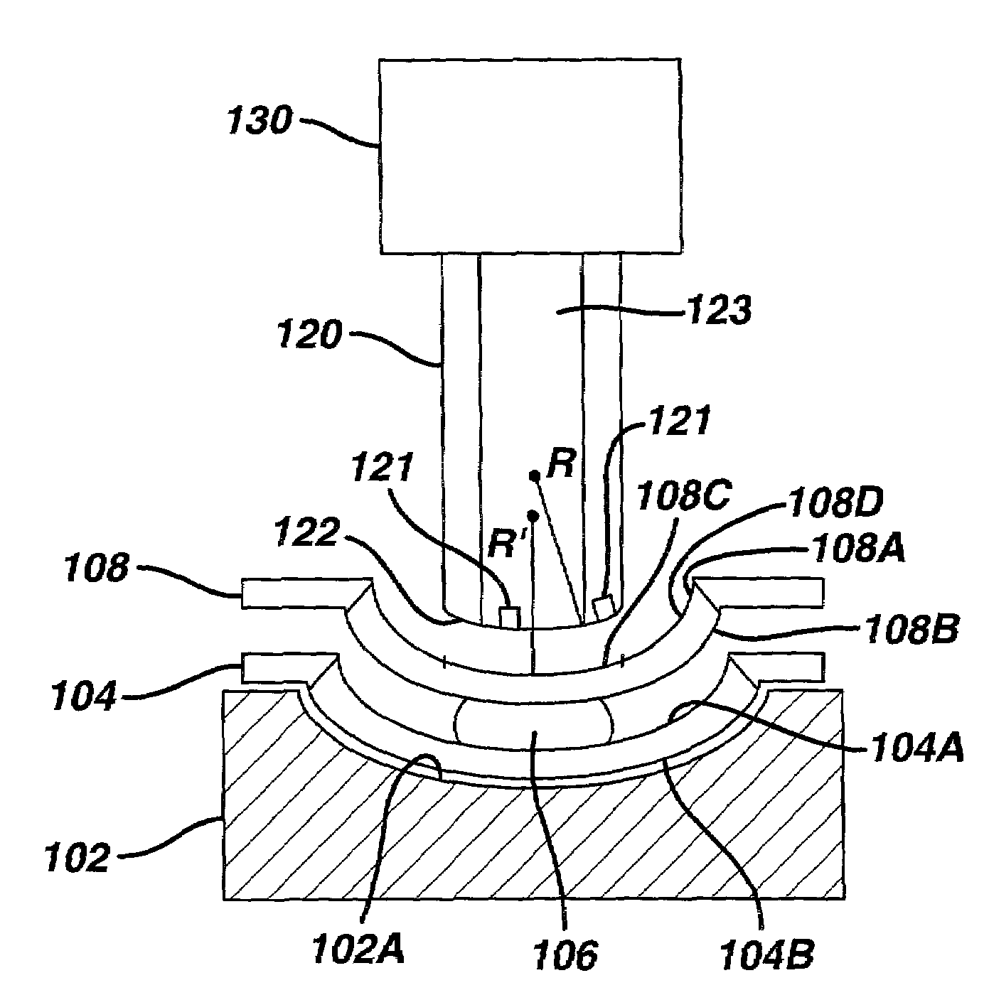
[0029]The present invention relates to an engaging method and apparatus for engaging a contact lens mold assembly used to form a contact lens. FIG. 3A depicts an embodiment of a molding apparatus for forming a contact lens in accordance with the present invention. The molding apparatus comprises a contact lens mold assembly (consisting of a front curve mold half 104 and a back curve mold half 108 which define a contact lens forming cavity for forming a contact lens therebetween), a carrier 102, a center touch engaging member 120, and a drive mechanism 130. The front curve mold half 104 is supported by the carrier 102 and the center touch engaging member 120 is configured to engage the back curve mold half 108. A liquid contact lens material 106 positioned between the front curve mold half 104 and the back curve mold half 108 forms a contact lens therebetween during molding. The drive mechanism 130 positions the center touch engaging member 120 and the carrier 102 relative to one ano...


PUM

PropertyMeasurementUnit
areaaaaaaaaaaa
molding areaaaaaaaaaaa
moldingaaaaaaaaaa

Abstract

A center touch method and apparatus for use in a contact lens station for use with a contact lens mold assembly comprising a first mold half and a second mold half. The center touch apparatus comprises a center touch engaging member having a center touch engaging surface for engaging a central portion of a non-molding surface of one of the mold halves. The center touch method comprising driving one of the mold halves toward the other mold half using the center touch engaging member to contact a central area of the non-molding surface of the one mold half.

Description

FIELD OF THE INVENTION[0001]The present invention relates to contact lenses and, more particularly, to a method and apparatus for engaging a contact lens mold used to form a contact lens.BACKGROUND OF THE INVENTION[0002]Contact lens molds are used to form contact lenses in contact lens production systems. The contact lens molds consist of two mold halves which define a contact lens forming cavity therebetween. During production, a solidifiable contact lens material in liquid form is deposited into a first mold half and the other mold half is positioned over the first mold half. Mold engaging apparatus then closes the mold to shape and cure the liquid contact lens material to form a contact lens. To ensure that a suitable contact lens is manufactured, it is important that the two mold halves are mated precisely. If the mold halves are not mated precisely, lens abnormalities may result which could cause discomfort to the wearer and / or not accurately correct the wearer's vision.[0003]F...

Claims


Application Information

Patent Timeline
Patent Type & Authority Patents(United States)
IPC IPC(8): B29D11/00B29C33/00G02C7/04B29C39/26B29C43/02B29L11/00
CPCB29D11/005Y10S425/808B29D11/00B29C33/00
Inventor DUBEY, DHARMESH K.SCHLAGEL, MARK E.WAGNER, ANDREW J.KIRK, JAMES F.
Owner JOHNSON & JOHNSON VISION CARE INC
Why Eureka
Try Eureka