Driving condition control method and system

Inactive Publication Date: 2007-07-10
DENSO CORP
View PDF12 Cites 2 Cited by
  • Summary
  • Abstract
  • Description
  • Claims
  • Application Information

AI Technical Summary

Benefits of technology

[0009]The present invention is made on the background for providing a driving condition control method an

Problems solved by technology

Even when the vehicle runs on a road surface that causes the vehicle's torque to be lost, th

Method used


Image

  • Driving condition control method and system
  • Driving condition control method and system
  • Driving condition control method and system

Examples


first embodiment

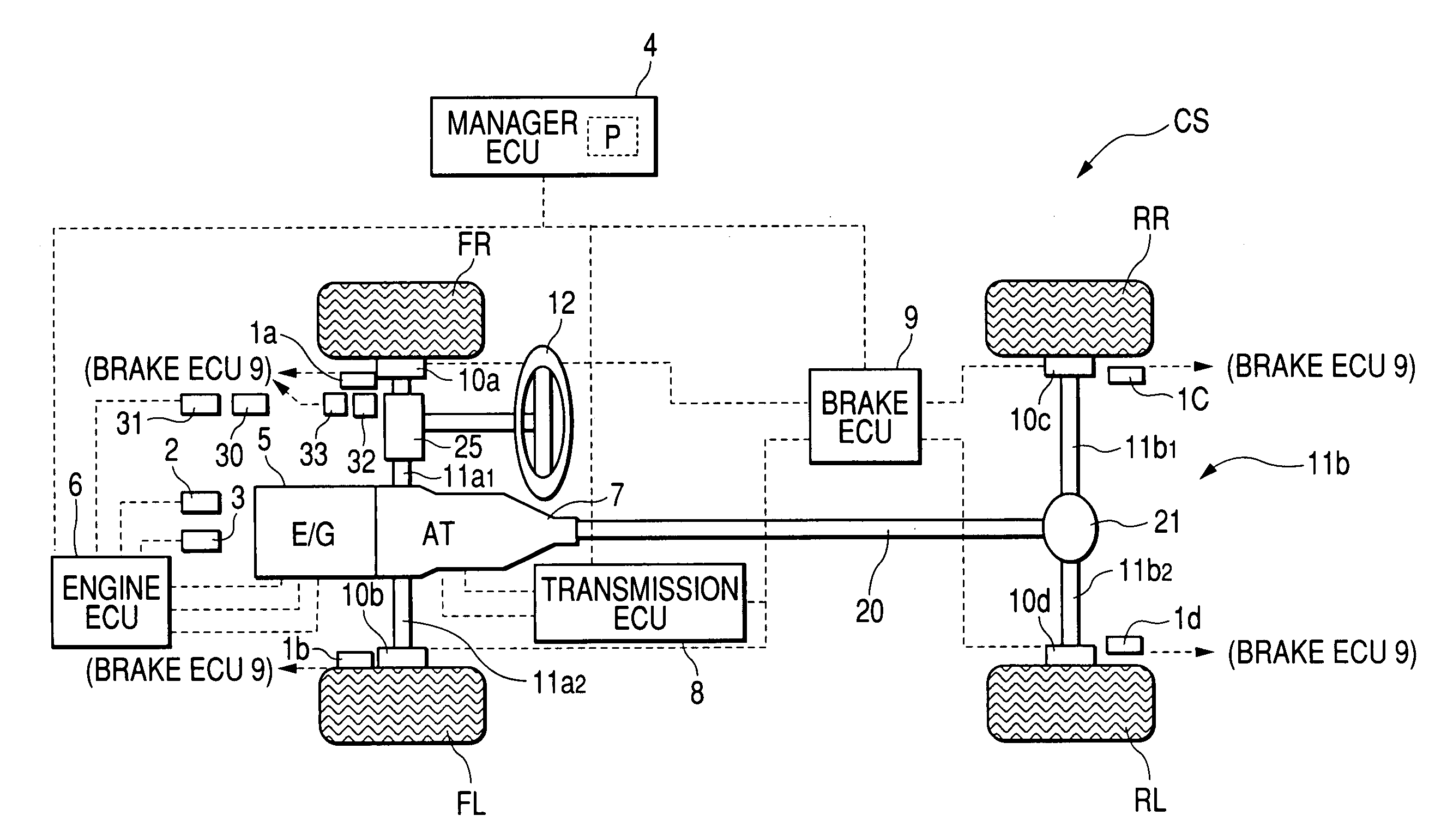
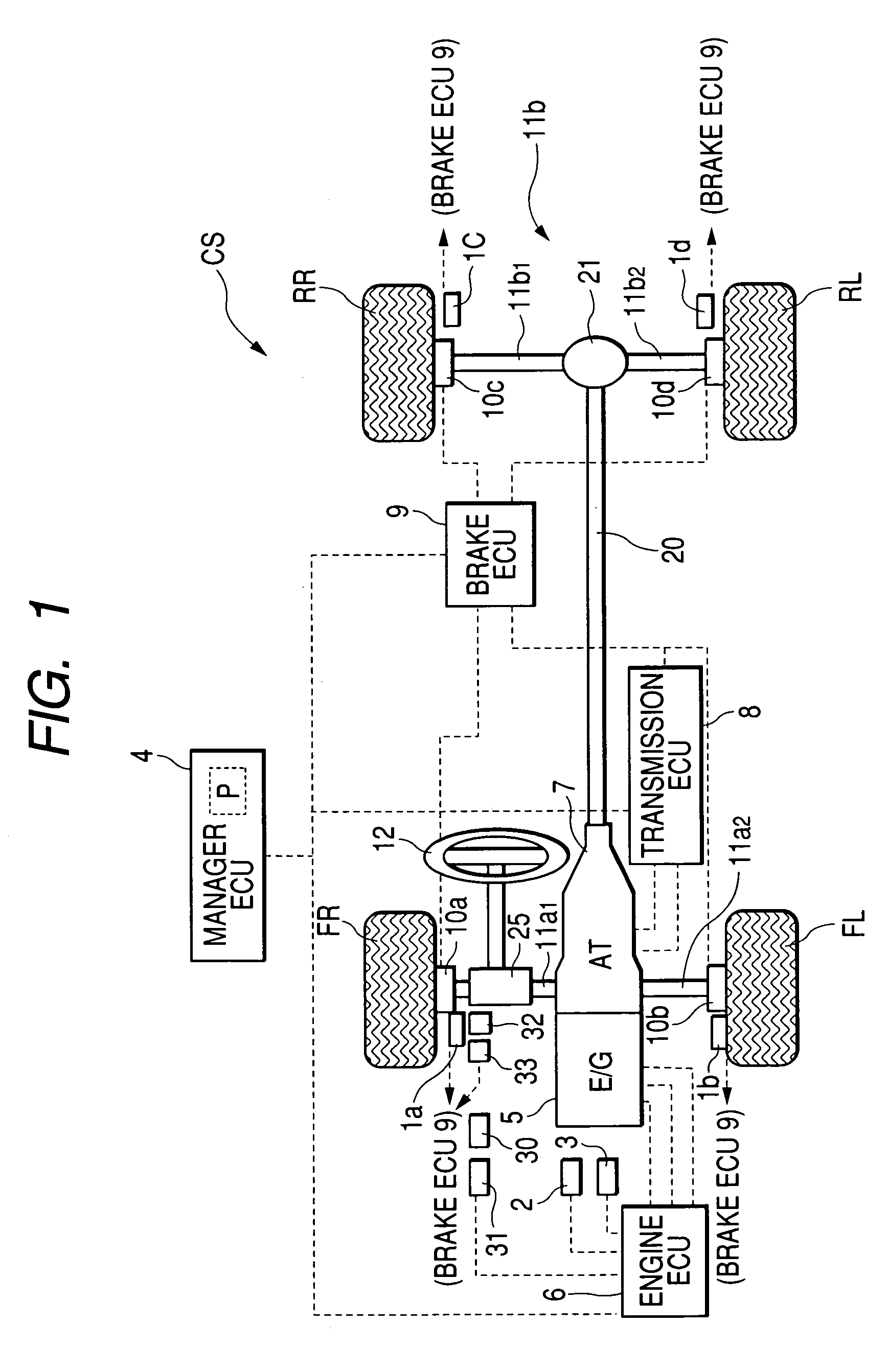
[0022]FIG. 1 is a schematic structural view of a driving condition control system according to a first embodiment of the present invention. The driving condition control system CS is installed in a vehicle, such as four-wheel automobile, V that is a type of front-engine-rear-drive vehicles.

[0023]That is, the vehicle V is provided with an engine 5, a drive shaft 20, and an automatic transmission (AT) 7 having a gear box and mechanically connected between the engine 5 and one end of the drive shaft 20. The AT 7 changes the gear ratios of the gear box independently of the driver to convert the engine's power output to torque based on the gear ratios, thereby transferring the torque to the drive shaft 20.

[0024]The vehicle V is also provided with a front axle assembly (rolling axle assembly) 11a and a rear axle assembly (drive axle assembly) 11b. The front axle assembly 11a has a supporting member, a right-front axle 11a1, and a left-front axle 11a2 that are individually rotatably suppor...

second embodiment

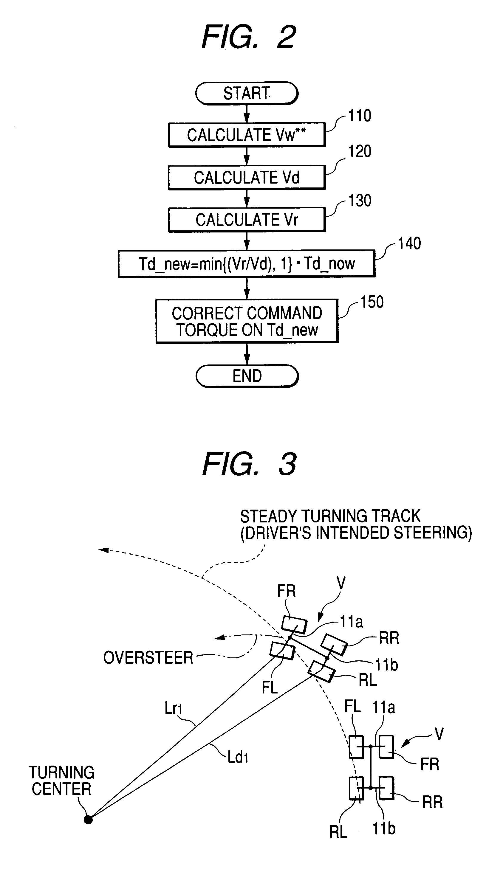
[0094]In the above mentioned first embodiment, the manager ECU 4 carries out the decreasing of the engine power (engine torque) to overcome the unstable conditions of the vehicle V.

[0095]In contrast, the manager ECU 4 of the driving condition control system according to the second embodiment adjusts the torque based on another processes.

[0096]That is, generating the brake force allows the torque to be adjusted except for the decrease of the engine power. In this second embodiment, the manager ECU 4 carries out the adjustment of the torque based on the braking forces.

[0097]Processes executed by the manager ECU 4 according to the second embodiment are partially different from those executed by the manager ECU 4 according to the first embodiment so that these partially different processes of the management ECU 4 according to the second embodiment will be explained hereinafter. The remaining processes and the structure of the driving condition control system according to the second embo...


PUM


Abstract

In a driving condition control system, a sensing unit is configured to sense a first physical quantity indicative of a rotation of the first rotatable axle assembly and a second physical quantity indicative of a rotation of the second rotatable axle assembly. A correcting unit is configured to correct the torque according to the sensed first and second physical quantities of the rotations of the first and second rotational axle assemblies. This allows the torque to be precisely obtained.

Description

BACKGROUND OF THE INVENTION[0001]The present invention relates to a driving condition control method and system installed in a vehicle, which are capable of controlling the driving conditions of the vehicle.[0002]Conventional techniques for causing a target torque to follow up a change of an accelerator pedal's operating state by a driver's operation are disclosed in Japanese Unexamined Patent Publication No. H09-242862 and in Japanese Unexamined Patent Publication No. H10-329585.[0003]The technique disclosed in the former publication estimates the rising slope of a road surface according to accelerating resistance torque. The technique corrects the gear ratios of the automatic transmission (AT) of a vehicle, thereby keeping torque during the running of the vehicle on the rising slope of the road surface.[0004]The technique disclosed in the later publication obtains a steady target torque of a driving system of a vehicle according to a driving condition of the vehicle, and determine...

Claims


Application Information

Patent Timeline
IPC IPC(8): B60W10/04B60W10/18B60W10/00B60K28/16B60T8/175B60W10/06B60W10/10B60W10/184F02D29/00
CPCB60K28/16B60W10/06B60W10/11B60W10/184B60W30/045B60K28/165Y10T477/814B60W2520/26B60W2520/263B60W2520/28B60W2710/0666B60W2710/105Y10T477/644Y10T477/817Y10T477/81Y10T477/816B60W2540/18
Inventor SAWADA, MAMORUMATSUMOTO, TOSHIKITASHIRO, TSUTOMUMABUCHI, MAMORUFUJII, TAKEHITOKATAOKA, MOTOAKI
Owner DENSO CORP
Why Eureka
Try Eureka