Device for tissue characterization

a tissue and device technology, applied in the field of tissue characterization devices, can solve the problems of inability to see by visible light, certain types of vulnerable plaques in the vasculature of patients, and the risk of rupture of certain types of vulnerable plaques

Inactive Publication Date: 2007-07-10
MEDEIKON
View PDF22 Cites 91 Cited by
  • Summary
  • Abstract
  • Description
  • Claims
  • Application Information

AI Technical Summary

Benefits of technology

[0015]The probe may further include a transparent housing intermediate to the outer periphery of each optical fiber and the optical element. The plurality of optical fibers may be embedded in or mounted on an inner surface wall of the housing. The plurality of optical fibers may be non-rotating. The plurality of optical fibers may include a central optical fiber or may include a hollow or solid structure having the same diameter as the optical fibers. The optical element may be transparent and may be continuous. The optical element may have a thickness of about 50 μm to about 5 mm. The optical element may be solid or may include a balloon having clear fluid. The probe may be utilized in interferometry such as low-coherence interferometry or spectroscopy applications. The tissue may be a vascular wall. The probe may allow blood flow to be maintained around the optical element.
[0021]The plurality of optical fibers may be non-rotating. The plurality of optical fibers may include a central optical fiber or may include a hollow or solid structure having the same diameter as the optical fibers. The optical element may be located adjacent an outer surface of the plurality of optical fibers. The system further includes at least one of a beam-shaping element and a redirection element. The optical element may have a thickness of about 50 μm to about 5 mm. The system may be utilized in low-coherence interferometry or spectroscopy applications. The system may allow blood flow to be maintained around the optical element.

Problems solved by technology

Certain types of vulnerable plaques in a patient's vasculature are likely to rupture.
These plaques, once ruptured, are extremely dangerous and can swiftly cause the patient's death.
Because these lipid pools are covered by vascular walls, they cannot be seen by visible light.
A difficulty associated with intravascular use of infrared radiation is that blood absorbs and scatters such radiation.
One drawback of OCT imaging is the time to acquire a large number of data points necessary to obtain an image over a sufficient area.
However, once the saline disperses, blood flows back into the measurement site and obscures the vascular wall.
However, if the balloon is not sufficiently inflated, considerable blood remains between the balloon and the vascular wall.
If the balloon is so inflated that it makes contact with the vascular wall, blood flow is obstructed.
This can lead to ischemia at points downstream from the balloon.
In addition, the pressure of the balloon on the vascular wall can trigger a rupture of the plaque.

Method used


Image

  • Device for tissue characterization
  • Device for tissue characterization
  • Device for tissue characterization

Examples


Embodiment Construction

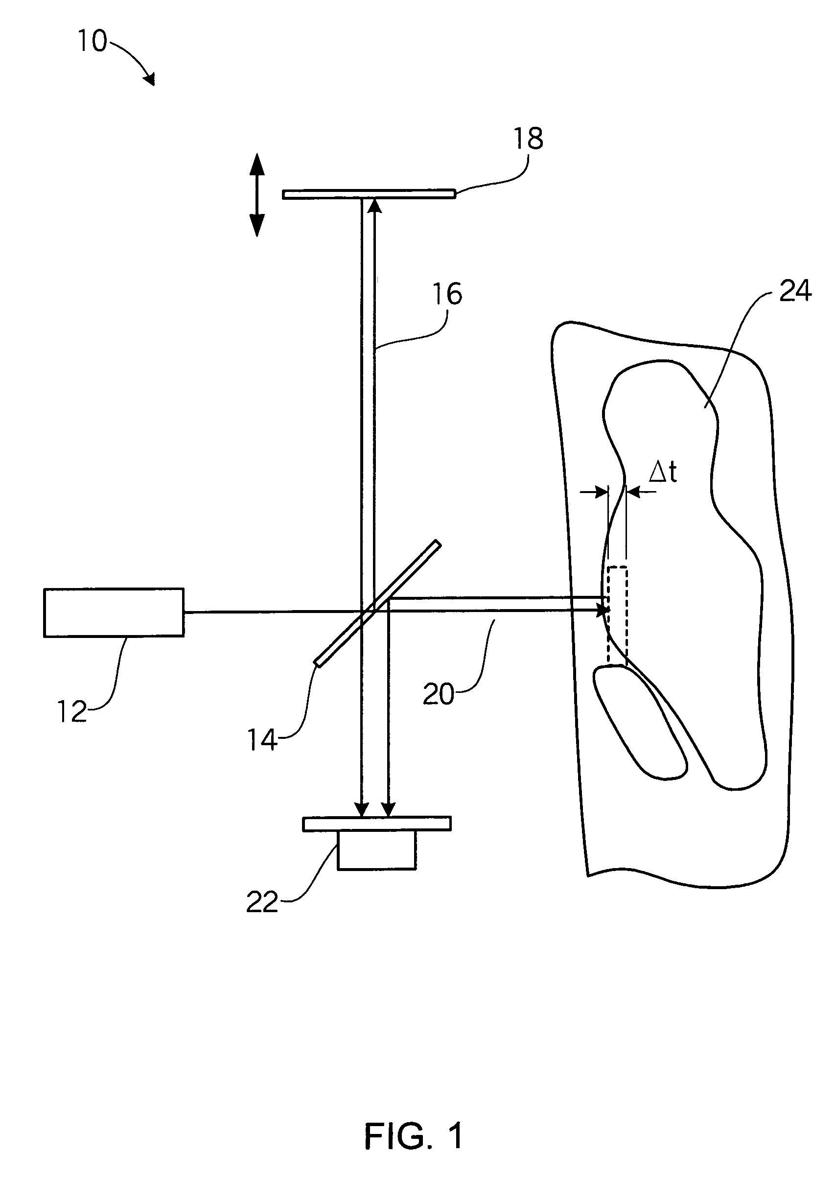
[0032]The invention generally relates to a device and system that probes arterial tissue and a method of doing the same. In particular, the use of an optical element in a device over a portion of a light path reduces the optical path length through the blood, thereby increasing the signal-to-noise ratio. For example, FIG. 1 illustrates LCI, a system based on fiber optics, used to probe a tissue sample in blood. While FIG. 1 illustrates light in an interferometer propagating in free space, implementations based on fiber optics or waveguides may also be utilized. The LCI system 10 in FIG. 1 includes a broadband source light 12, a beamsplitter 14, a reference arm 16, a movable mirror 18, a sample arm 20, a detector system 22, and an object or tissue being examined 24. The beamsplitter 14 splits the source light 12 and directs it into two paths, a path that extends onto the tissue or object being measured along sample arm 20, and another path that reflects off the movable mirror 18 alon...


PUM


Abstract

A probe for use in characterizing tissue. The probe includes a plurality of optical fibers and an optical element. Each fiber includes a distal portion and a proximal portion. The fibers transmit light through the fiber to a surrounding area and collect light reflected back from the surrounding area. The optical element may be adjacent an outer periphery of the distal portion of the plurality of optical fibers. The optical element reduces an optical path length through blood.

Description

CROSS-REFERENCE TO RELATED APPLICATION[0001]This application claims the benefit of U.S. Provisional Patent Application No. 60 / 591,279, filed Jul. 27, 2004 which is hereby incorporated by reference in its entirety.BACKGROUND[0002]1. Field of the Invention[0003]The invention relates generally to inspection instruments, and more particularly to a system and device for detecting and characterizing tissue and a method thereof.[0004]2. Description of Related Art[0005]Certain types of vulnerable plaques in a patient's vasculature are likely to rupture. These plaques, once ruptured, are extremely dangerous and can swiftly cause the patient's death. It is therefore desirable to detect the existence of such high-risk plaques so that they can be disposed of before they rupture.[0006]High-risk plaques are believed to be characterized by large lipid pools hidden behind vascular walls. Because these lipid pools are covered by vascular walls, they cannot be seen by visible light. However, infrared...

Claims


Application Information

Patent Timeline
Patent Type & Authority Patents(United States)
IPC IPC(8): G02B6/06A61B19/00A61B6/00G01B9/02
CPCA61B5/0066A61B5/02007A61B5/6852G01N21/45G02B6/26A61B5/0084A61B5/0086
Inventor CARLIN, DONALD B.ALPHONSE, GERARD A.
Owner MEDEIKON
Why Eureka
Try Eureka