Optical component and optical transmitter-receiver for use in two-way optical communication

a technology of optical components and optical transmitters, applied in the direction of optical elements, semiconductor lasers, instruments, etc., can solve the problems that the device described above cannot avoid causing crosstalk, and achieve the effect of reducing far-end crosstalk

Inactive Publication Date: 2007-07-10
HOSIDEN CORP
View PDF5 Cites 0 Cited by
  • Summary
  • Abstract
  • Description
  • Claims
  • Application Information

AI Technical Summary

Benefits of technology

[0021]In view of the foregoing situation, it is an object of this invention to provide an optical component for two-way optical communication which is configured to significantly reduce far-end crosstalk, and an optical transmitter-receiver having such optical component incorporated therein.

Problems solved by technology

It should be here appreciated that in this type of optical component in charge of both transmission and reception of light, crosstalk is a great concern with respect to its performance and that it is a significant problem to suppress the crosstalk.
That is, the previous device described above cannot avoid causing crosstalk.

Method used


Image

  • Optical component and optical transmitter-receiver for use in two-way optical communication
  • Optical component and optical transmitter-receiver for use in two-way optical communication
  • Optical component and optical transmitter-receiver for use in two-way optical communication

Examples


Embodiment Construction

[0034]Embodiments of this invention will now be described by way of example with reference to the accompanying drawings, in which the parts which correspond to those shown in FIGS. 6A-6B are designated by like reference numerals and will not be discussed again in detail.

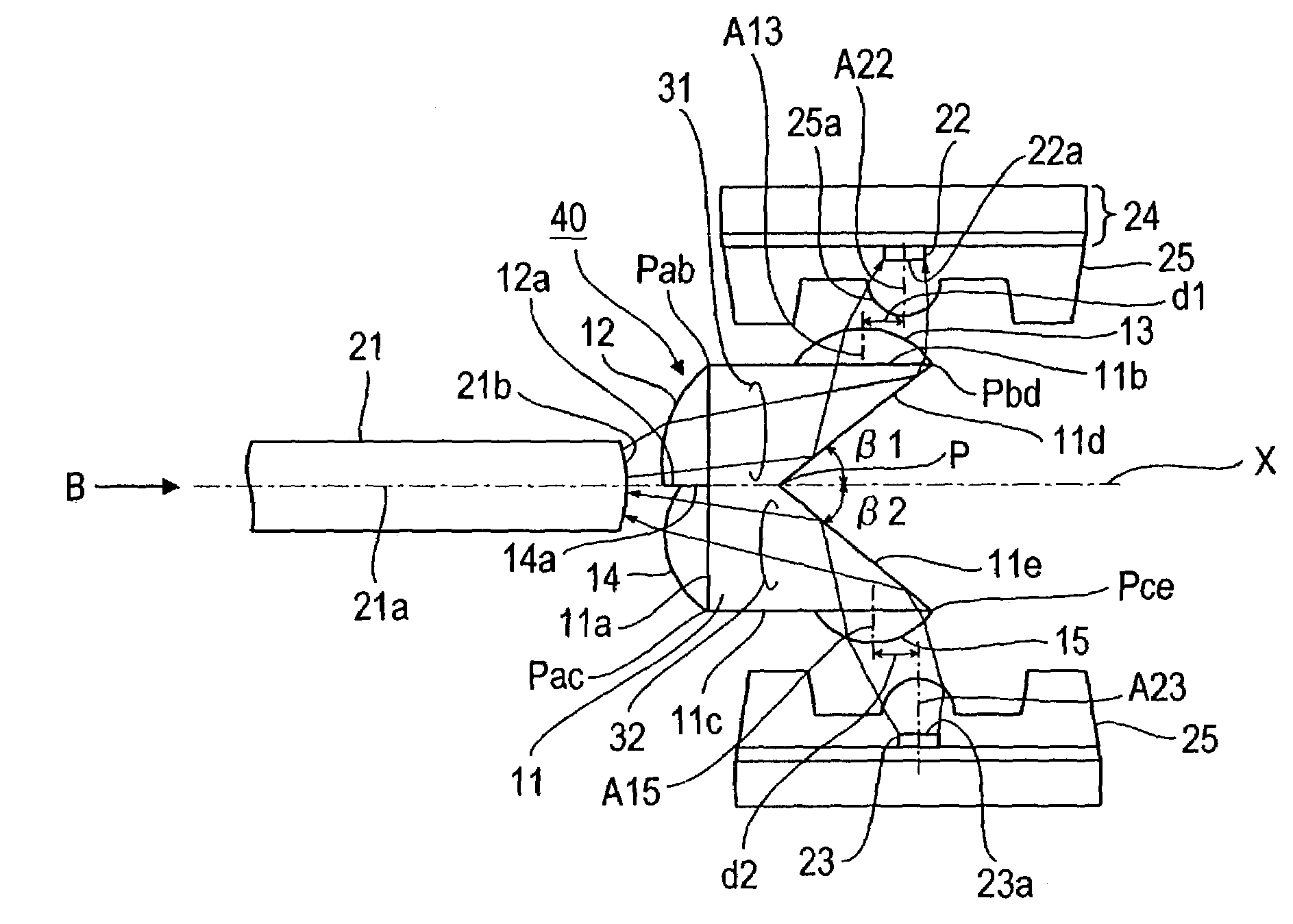
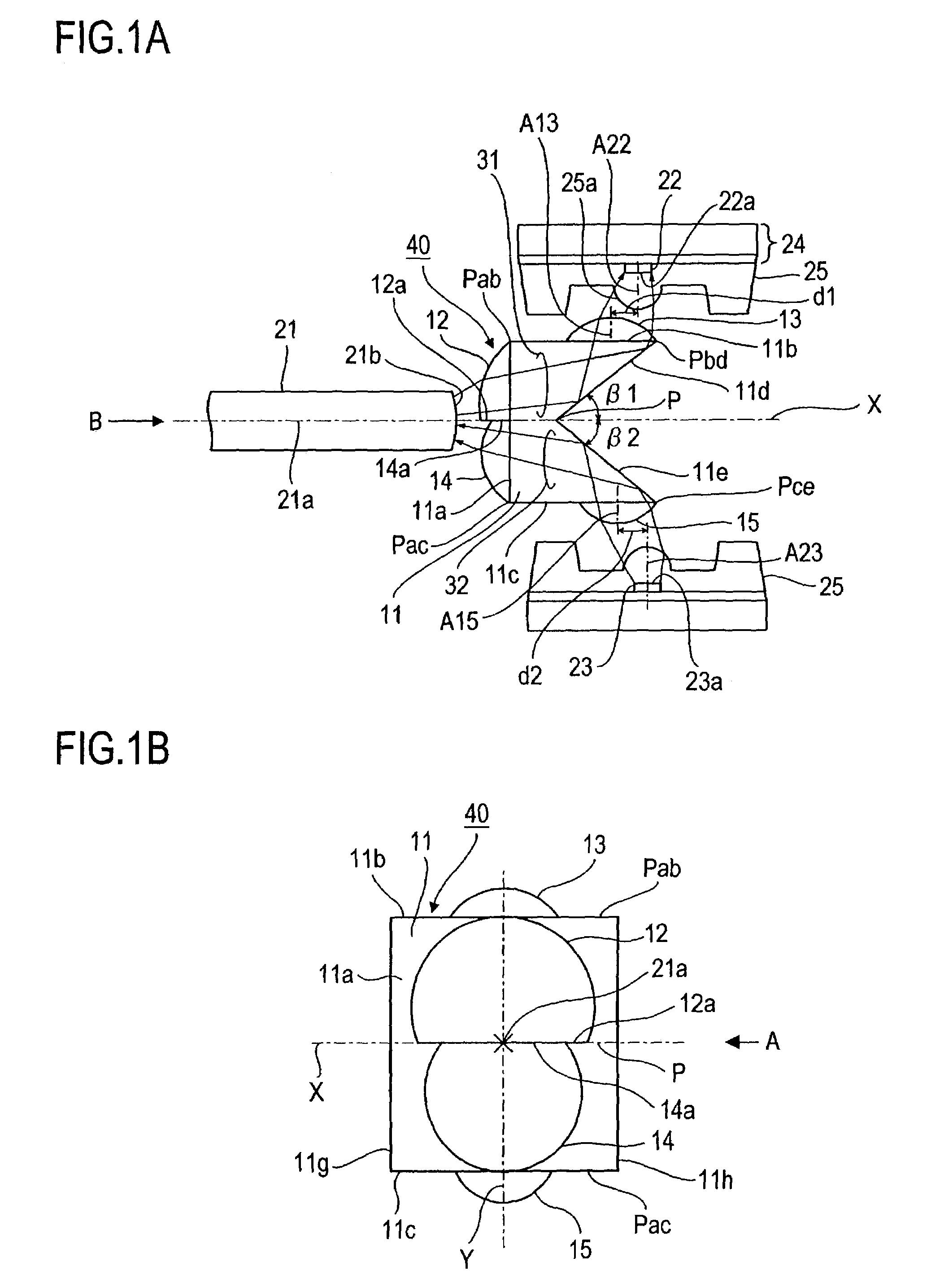
[0035]FIGS. 1A-1B illustrate one embodiment of the optical component 40 for two-way optical communication according to this invention and the optical transmitter-receiver constructed by combining the optical component 40 with a light-receiving element 22 and a light-emitting element 23. In this example, the optical component 40 comprises a prism 11 having a pentagular shape in cross-section generally similar to that of the prism 11 of the optical component 10 shown in FIGS. 6A-6B and having lens 12-15 formed integrally on the faces. In FIG. 1A, the one-dotted chain line indicates an axis 21A of an optical fiber 21 positioned in conjunction with the optical component 40.

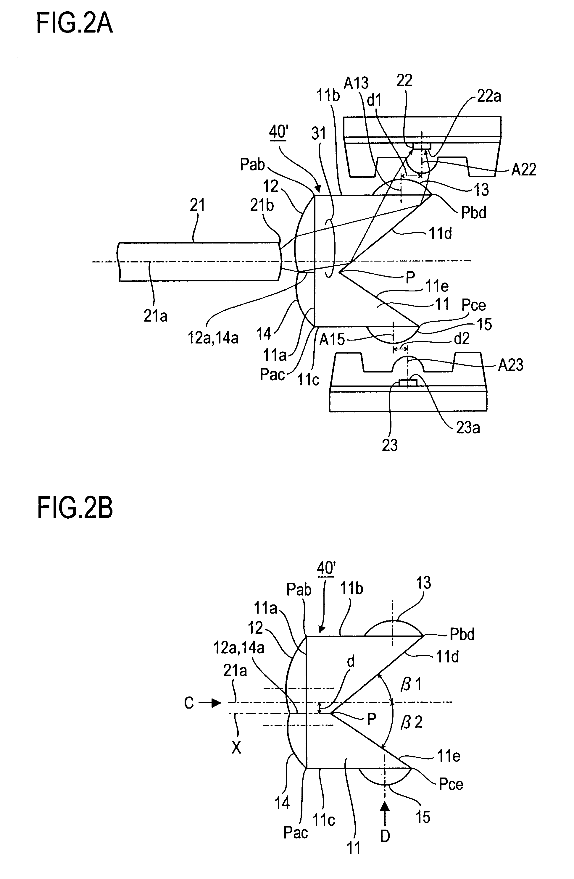
[0036]The prism 11 of this embodiment differs fr...


PUM


Abstract

A prism 11 is formed which has a first face 11a opposing an end face of an optical fiber 21 and receiving a light-to-be-received from the optical fiber, second and third faces 11b and 11c adjoining opposite ends of the first face 11a at right angles and opposing each other, a fourth face 11d for reflecting the light-to-be-received from the face 11a toward the face 11b, and a fifth face 11e reflecting a light-to-be-transmitted as projected from a light source through the face 11c toward the face 11a. First and second light-to-be-received converging lenses 12 and 13 are disposed on the faces 11a and 11b of the prism 11 and first and second light-to-be-transmitted converging lenses 14 and 15 are disposed on the faces 11a and 11c. The tilt angles β1 and β2 of the faces 11d and 11e with respect to the optical fiber axis 21a are less than 45°. With this configuration, if the light-to-be-received enters the light-receiving element 22 and the light-emitting element 23 and is reflected by these elements, such reflected light is prevented from returning back into the optical fiber whereby occurrence of far-end crosstalk can be suppressed.

Description

BACKGROUND OF THE INVENTION[0001]1. Field of the Invention[0002]This invention relates to an optical component for use in two-way optical communication in which transmission and reception of light are effected through a single optical fiber, and an optical transmitter-receiver constructed by the use of the optical component.[0003]2. Description of the Related Art[0004]FIGS. 6A and 6B illustrate a previous optical component (which will be referred to as previous device hereinafter) of the type concerned which has been devised in the factory facilities of the assignee of the present patent application, although not publicly known and from which the present invention originated, and an optical transmitter-receiver constructed by incorporating the component therein together with an optical fiber and light-receiving and light-emitting elements. This previous device will be described below as an example of comparison merely for facilitating of the understanding of the present invention.[0...

Claims


Application Information

Patent Timeline
Patent Type & Authority Patents(United States)
IPC IPC(8): H04B10/00G02B6/26G02B5/04G02B6/42H01L31/0232H01L33/00H01L33/54H01S5/022
CPCG02B6/4201G02B6/4206G02B6/4214H04B10/40G02B6/4246G02B6/4292H01S5/4012G02B6/42
Inventor MINE, KEIJINAKAGAWA, HIROSHIISODA, TAKESHI
Owner HOSIDEN CORP
Why Eureka
Try Eureka