Micro-strip transmission line structure of a serpentine type

Inactive Publication Date: 2010-08-19
POSTECH ACAD IND FOUND
View PDF6 Cites 8 Cited by
  • Summary
  • Abstract
  • Description
  • Claims
  • Application Information

AI Technical Summary

Benefits of technology

[0018]The present invention provides a structure of a micro-strip transmission line having a serpentine shape capable of reducing far-end crosstalk of a transmission line by increasing capacitive coupling between neighboring transmission lines by allowing parallel micro-strip transmission lines to have serpentine shapes.

Problems solved by technology

Crosstalk is caused by electromagnetic interference between neighboring signal lines.
When a high frequency signal is transmitted through two parallel long signal lines, signals transmitted through one or two signal lines mutually interfere with one another.
A transmission loss is increased due to the crosstalk caused by the mutual interference.
Accordingly, costs are increased.
However, in the aforementioned methods, the micro-strip transmission lines occupy too large area in the PCB.

Method used


Image

  • Micro-strip transmission line structure of a serpentine type
  • Micro-strip transmission line structure of a serpentine type
  • Micro-strip transmission line structure of a serpentine type

Examples


Embodiment Construction

[0031]Hereinafter, the present invention will be described in detail by explaining exemplary embodiments of the invention with reference to the attached drawings.

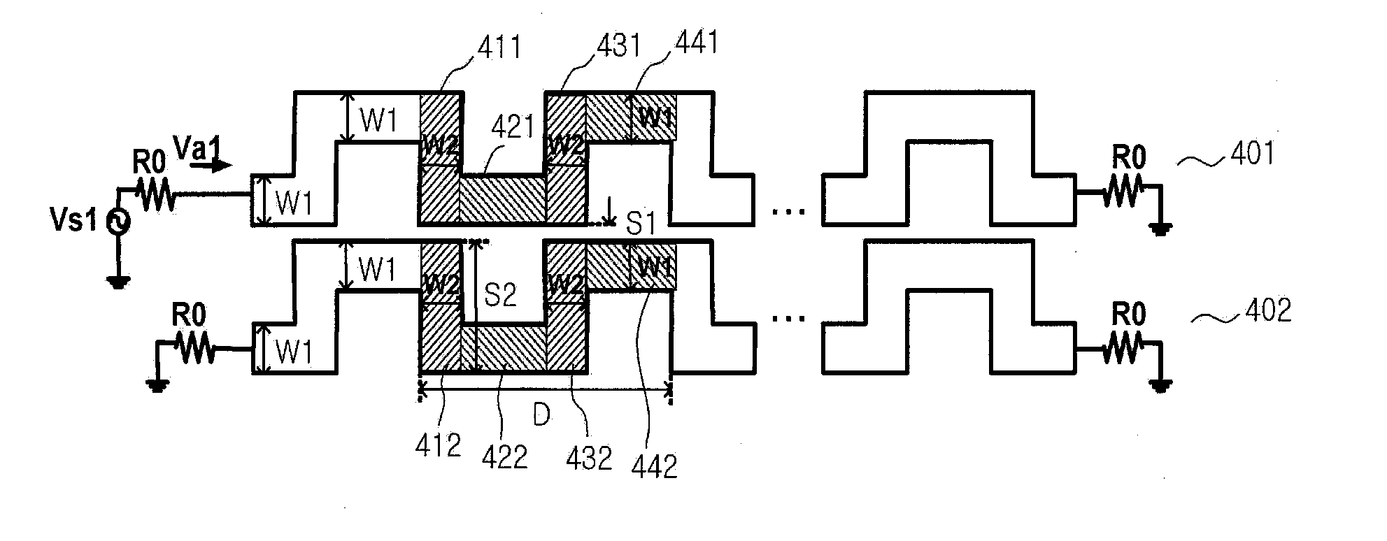
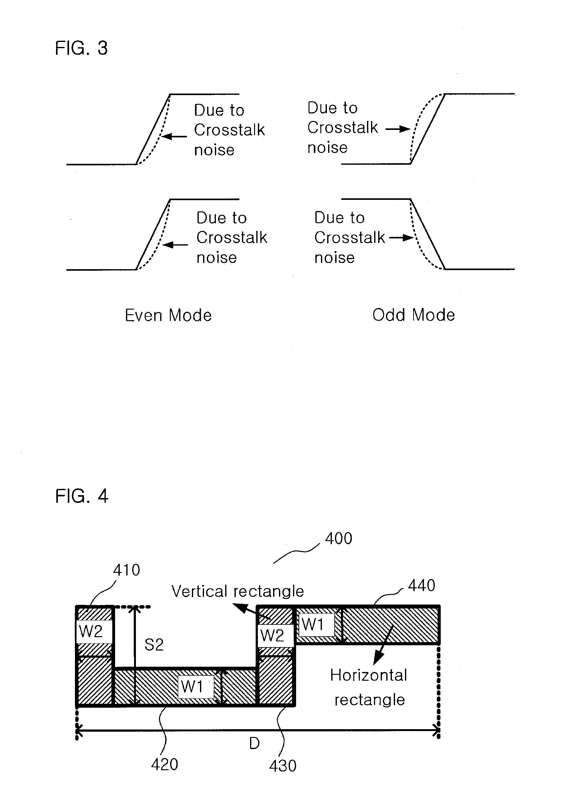
[0032]FIG. 4 illustrates a unit serpentine structure of a structure of a micro-strip transmission line having a serpentine shape according to an embodiment of the present invention.

[0033]As shown in FIG. 4, a serpentine structure 400 according to the embodiment of the present invention includes a first vertical micro-strip transmission line 410, a first horizontal micro-strip transmission line 420, a second vertical micro-strip transmission line 430, and a second micro-strip transmission line 440.

[0034]Unlike a structure of conventional micro-strip transmission lines that are parallel straight lines, if a serpentine structure is used, mutual capacitance between neighboring signal lines is increased. In the serpentine structure, since a component perpendicular to a length direction of a micro-strip transmission line is perpe...


PUM


Abstract

A micro-strip transmission line capable of reducing far-end crosstalk is provided. The micro-strip transmission line having a serpentine shape is capable of reducing the far-end crosstalk of the transmission line by increasing capacitive coupling between neighboring transmission lines by allowing parallel micro-strip transmission lines to have serpentine shapes. In the structure of the micro-strip transmission line having the serpentine shape, it is possible to reduce the far-end crosstalk of the transmission line by increasing capacitive coupling between neighboring transmission lines by allowing parallel micro-strip transmission lines to have serpentine shapes.

Description

BACKGROUND OF THE INVENTION[0001]1. Field of the Invention[0002]The present invention relates to a micro-strip transmission line capable of reducing far-end crosstalk, and more particularly, to a structure of a micro-strip transmission line having a serpentine shape for reducing far-end crosstalk of a transmission line by increasing capacitive coupling between neighboring transmission lines by allowing parallel micro-strip transmission lines to have serpentine shapes.[0003]2. Description of the Related Art[0004]Crosstalk is caused by electromagnetic interference between neighboring signal lines. When a high frequency signal is transmitted through two parallel long signal lines, signals transmitted through one or two signal lines mutually interfere with one another. A transmission loss is increased due to the crosstalk caused by the mutual interference.[0005]Capacitive coupling caused by mutual capacitance and inductive coupling caused by mutual inductance occur between the two signa...

Claims


Application Information

Patent Timeline
IPC IPC(8): H01P3/08
CPCH01P3/081H05K1/0216H05K2201/09263H05K2201/09236H05K1/0237H01P3/08
Inventor PARK, HONG-JUNELEE, KYOUNG-HO
Owner POSTECH ACAD IND FOUND
Why Eureka
Try Eureka