Optical device for double-path optical communication and op-tical emitting-receiving machine

An optical element, dual-path optical technology, applied in the direction of optical elements, optics, electrical elements, etc., can solve the problems of unavoidable crosstalk, far-end crosstalk, etc.

Inactive Publication Date: 2004-01-28
HOSIDEN CORP
View PDF0 Cites 8 Cited by
  • Summary
  • Abstract
  • Description
  • Claims
  • Application Information

AI Technical Summary

Problems solved by technology

That is to say, the above-mentioned prior device cannot avoid generation of crosstalk
More specifically, due to the Figure 7 A study of the causes of the crosstalk shown has found that due to the inclination angles α1 and α2 of the surfaces (reflecting surfaces) 11d and 11e, respectively, relative to the plane X passing through the corner P and the axis 21a of the optical fiber 21 and perpendicular to the plane on which the figure is located, both set be relatively large, namely 45°, the light ray 31 to be received can enter the corresponding surfaces 22a and 23a of the light receiving element 22 and the light emitting element 23, and the light reflected by these element surfaces can follow it again before returning to the optical fiber 21. along its incoming path, thus causing far-end crosstalk to stations on the other side
[0018] In addition, since the light-receiving element 22 and the light-emitting element 23 are positioned directly opposite to the lenses 13 and 15, respectively, and the centers A22 and A23 of these elements are aligned with the central axes 13a and 15a of the lenses 13 and 15, respectively, the prior The device also causes the light reflected by the surfaces of these components to re-follow the path it had entered along before returning to the fiber 21, thus easily causing far-end crosstalk at the other side station

Method used


Image

  • Optical device for double-path optical communication and op-tical emitting-receiving machine
  • Optical device for double-path optical communication and op-tical emitting-receiving machine
  • Optical device for double-path optical communication and op-tical emitting-receiving machine

Examples


Embodiment Construction

[0032] Embodiments of the present invention will be discussed in detail by way of example with reference to the accompanying drawings, in which and Figures 6A-6B Corresponding parts are marked with the same reference numerals and will not be described in detail again.

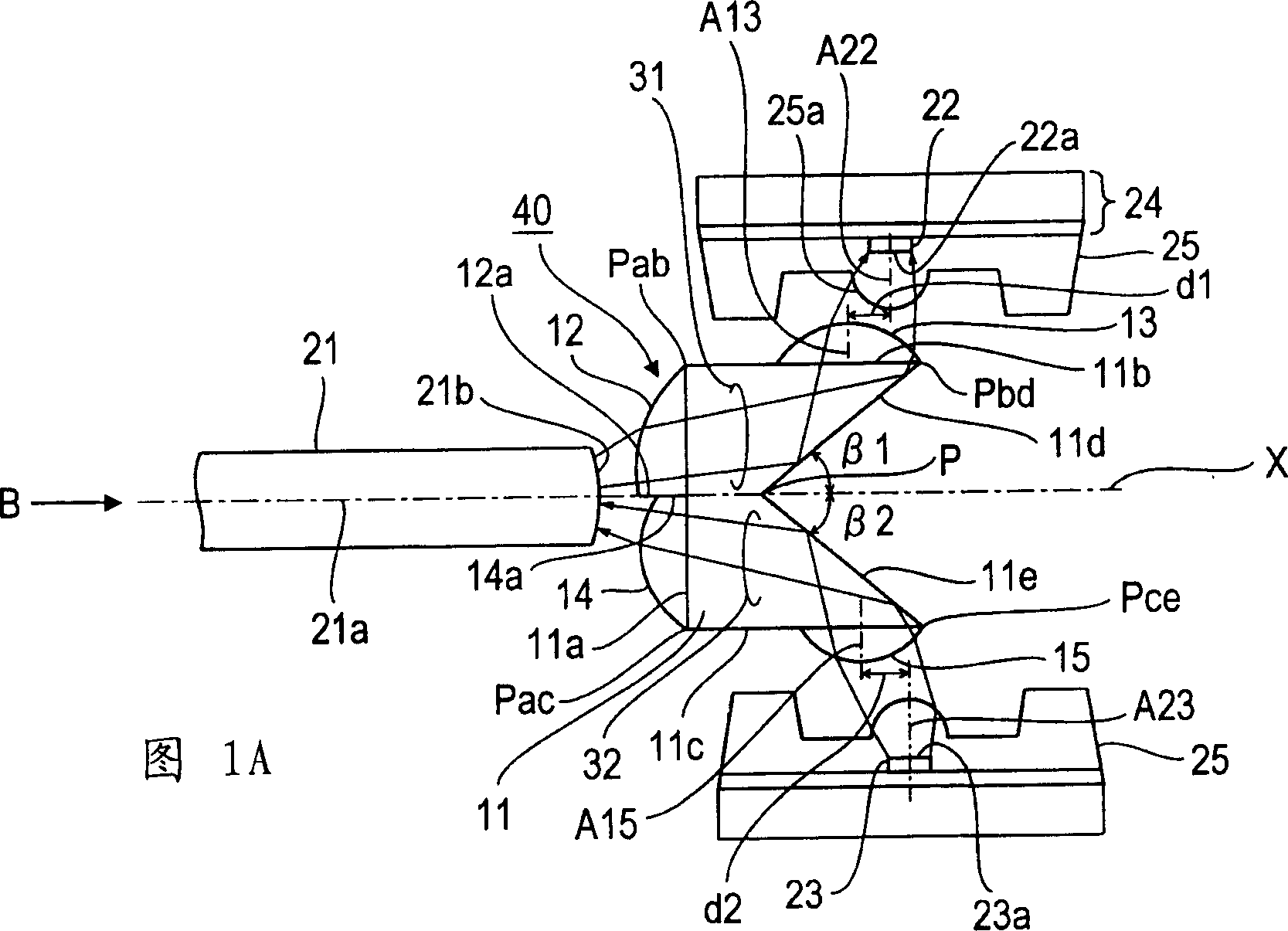
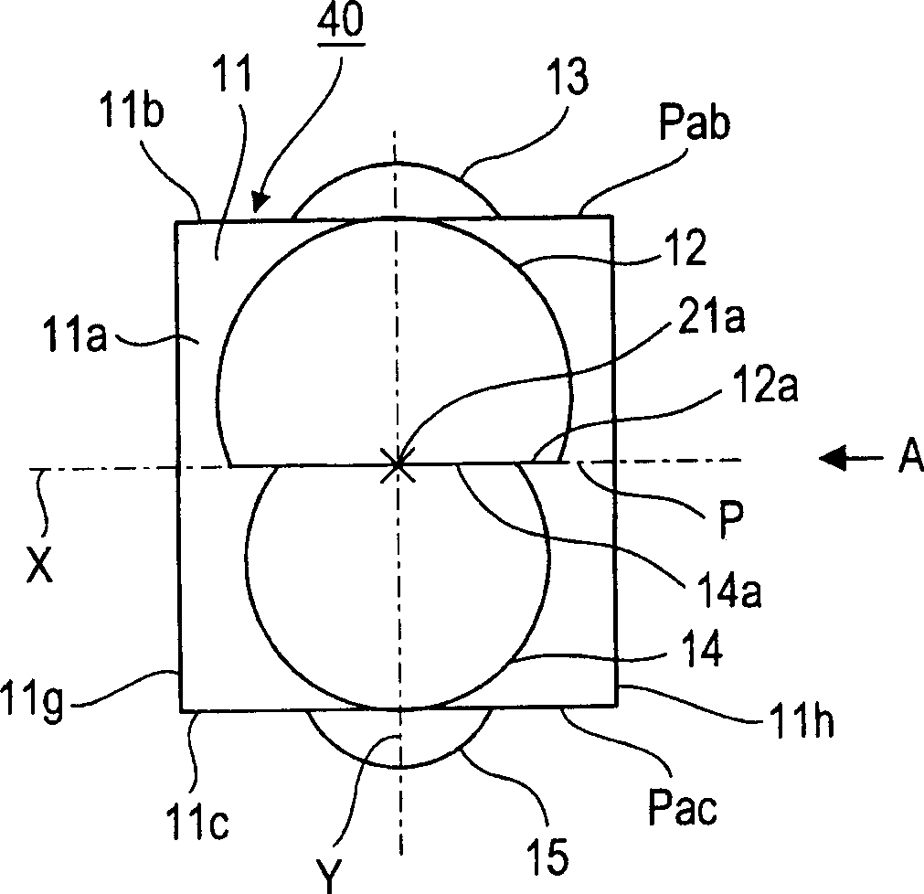
[0033] 1A-1B illustrate an embodiment of an optical element 40 for two-way optical communication according to the present invention, and an optical transmitter receiver formed by combining the optical element 40 with a light receiving element 22 and a light emitting element 23 . In this example, the optical element 40 includes a prism 11 having a cross-section corresponding to Figures 6A-6B The prism 11 in the optical element 10 shown has a similar pentagonal shape and has lenses 12-15 integrated on the surface. In FIG. 1A , a one-dot chain line indicates the optical axis 21 a of the optical fiber 21 positioned together with the optical element 40 .

[0034] The prism 11 of this embodiment differs from prio...


PUM


Abstract

Optical device for double-path optical communication. A prism 11 is formed which has a first face 11a opposing an end face of an optical fiber 21 and receiving a light-to-be-received from the optical fiber, second and third faces 11b and 11c adjoining opposite ends of the first face 11a at right angles and opposing each other, a fourth face 11d for reflecting the light-to-be-received from the face 11a toward the face 11b, and a fifth face 11e reflecting a light-to-be-transmitted as projected from a light source through the face 11c toward the face 11a. First and second light-to-be-received converging lenses 12 and 13 are disposed on the faces 11a and 11b of the prism 11 and first and second light-to-be-transmitted converging lenses 14 and 15 are disposed on the faces 11a and 11c. The tilt angles beta1 and beta2 of the faces 11d and 11e with respect to the optical fiber axis 21a are less than 45 DEG . With this configuration, if the light-to-be-received enters the light-receiving element 22 and the light-emitting element 23 and is reflected by these elements, such reflected light is prevented from returning back into the optical fiber whereby occurrence of far-end crosstalk can be suppressed.

Description

technical field [0001] The present invention relates to an optical element for dual-path optical communication, wherein the transmission and reception of light are realized through a single optical fiber, and also relates to an optical transmitter and receiver constituted by the optical element. Background technique [0002] Figure 6A and 6B Shown are related types of optical elements (hereinafter referred to as prior devices) which, although not known to the public, have been designed on the processing equipment of the assignee of the present application and upon which the present patented invention is based produce, Figure 6A and 6B Also shown is a light transmitting receiver constructed by combining optical elements, optical fibers, and light receiving and light emitting elements. The prior device will be described below as a comparative example only for the convenience of understanding the present invention. [0003] In the illustrated prior device, the optical elem...

Claims


Application Information

Patent Timeline
Patent Type & Authority Applications(China)
IPC IPC(8): G02B5/04G02B6/42H01L31/0232H01L33/00H01L33/54H01S5/022
CPCG02B6/4246G02B6/4214H01S5/4012G02B6/4206G02B6/4201G02B6/4292H04B10/40G02B6/42
Inventor 峰启治中川浩志礒田丈司
Owner HOSIDEN CORP
Why Eureka
Try Eureka