Clip

a clip and clip technology, applied in the field of clips, can solve the problems such as the difficulty of disengagement of the protruding piece from the shaft portion, and achieve the effect of reliably closing and removing the clip

Inactive Publication Date: 2007-07-17
PIOLAX CO LTD
View PDF11 Cites 18 Cited by
  • Summary
  • Abstract
  • Description
  • Claims
  • Application Information

AI Technical Summary

Benefits of technology

[0016]In accordance with the above-described invention, in the process of inserting the insertion member into the latch member, the projections and the hinge members are brought into contact with each other, and a situation is prevented in which the hinge members are bent in such a manner as to project downward. Therefore, at the time the clip is removed, the hinge members are pulled upward speedily together with the insertion member, so that both side leg portions can be closed reliably, thereby making it possible to remove the clip reliably.

Problems solved by technology

Accordingly, the shaft portion is tucked in by the retaining protruding piece of each side leg portion and the protruding side of the split flange and the retaining protruding piece engages with the shaft portion, so that the retaining protruding piece is difficult to disengage from the shaft portion.

Method used


Image

  • Clip
  • Clip
  • Clip

Examples


Embodiment Construction

[0024]Embodiments of the invention will be explained with reference to the drawings.

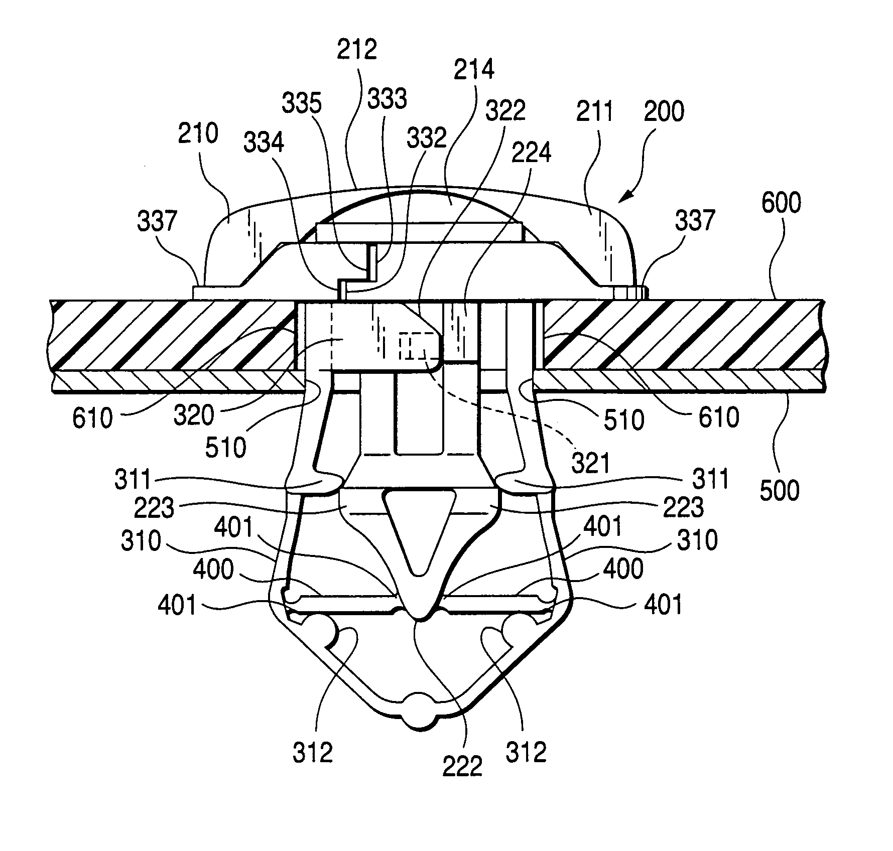
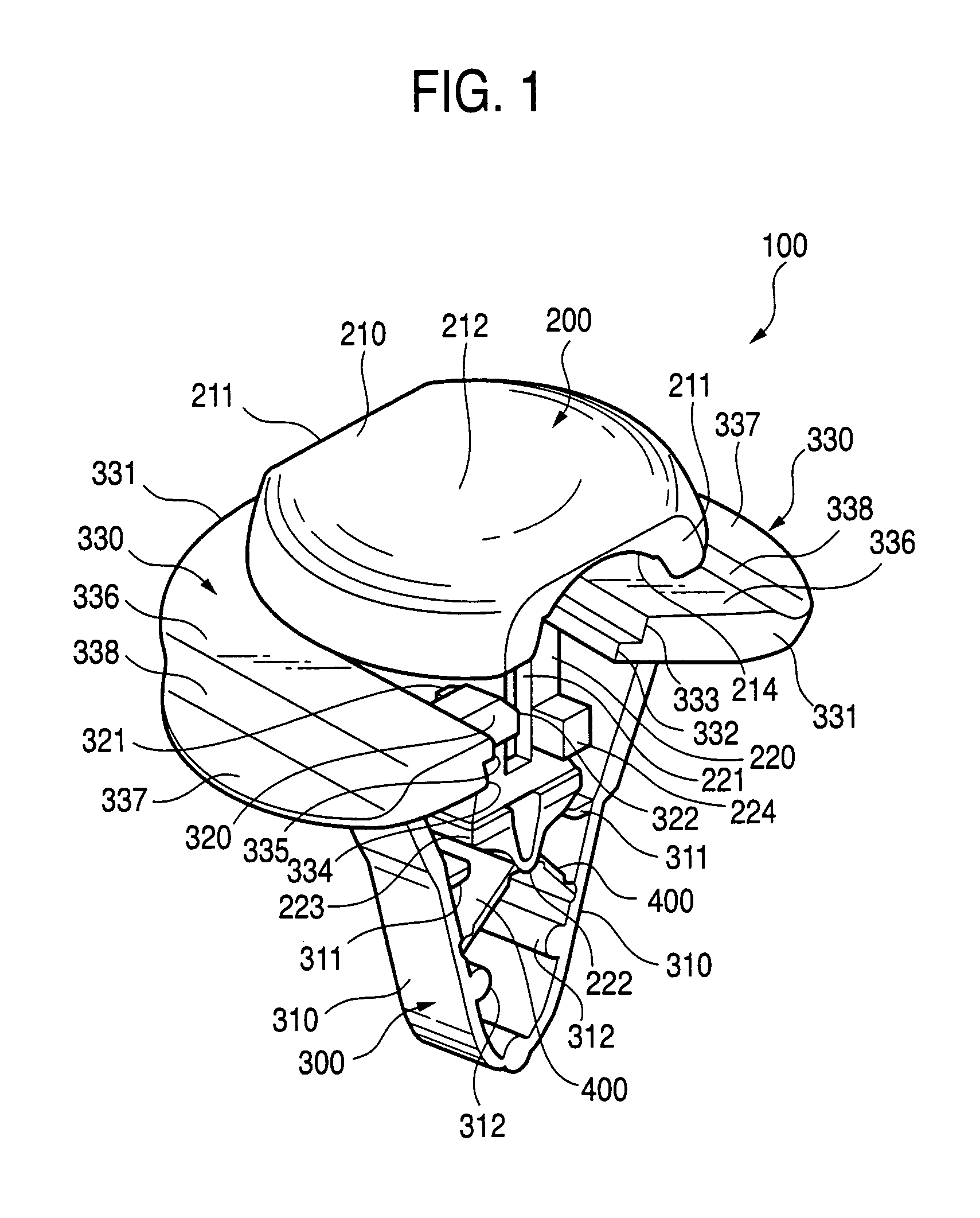
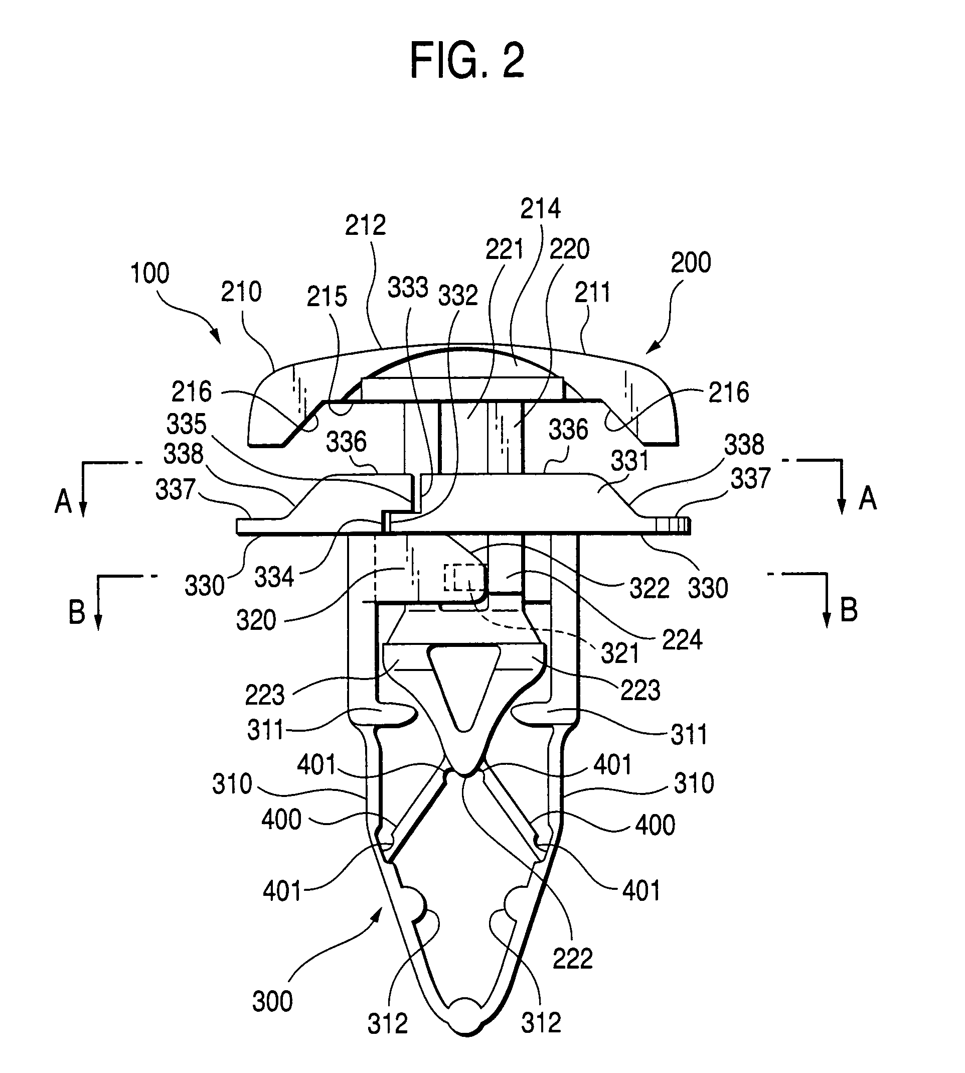
[0025]FIGS. 1 to 6 show an embodiment of a clip in accordance with the invention. FIG. 1 is a perspective view of a state in which both side leg portions of the clip are open. FIG. 2 is a side view of a state in which both side leg portions of the clip are closed. FIG. 3 is a cross-sectional view taken along line A—A in FIG. 2. FIG. 4 is a cross-sectional view taken along line B—B in FIG. 2. FIG. 5 is an explanatory view illustrating a state in which the clip is inserted in attaching holes of two plate members. FIG. 6 is an explanatory view illustrating a state in which the two plate members are fixed by pressing in the head portion of the clip.

[0026]As shown in FIGS. 1 and 2, a clip 100 has an insertion member 200 which includes a head portion 210 and a shaft portion 220 extending perpendicularly from the center of a lower surface of the head portion 210. Further, a latch member 300 in which both si...


PUM


Abstract

A clip includes an insertion member whose cross-sectional shape is in a T-shape, having a head portion and a shaft portion connected downwardly from the head portion; a latch member in a V-shape disposed on an outer side of the shaft portion; and a hinge member connecting the shaft portion and the latch member. Split flanges, mated in a flange-shape by surrounding the shaft portion when both side leg portions are closed, are provided to be continued from upper end portions of the both side leg portions. One side of an abutting surface of each split flange protrudes to form an L-shape in a plan view and abuts against a corresponding side portion of the shaft portion. A retaining protruding piece extending from a side portion opposite to a protruding portion and engaging with corresponding side portion of the shaft portion is formed on each both side leg portions.

Description

BACKGROUND OF THE INVENTION[0001]1. Field of the Invention[0002]The present invention relates to a clip in which an attaching hole formed in a unit to be attached is superposed on an attaching hole in an attaching unit, and the clip is inserted in these holes so as to connect the two units, thereby making it possible to fix them simply. The present invention especially relates to a clip in which an insertion member including a head portion and a shaft portion is connected to a latch member engaging on a reverse surface side of the attaching hole to be expanded in diameter by pressing the insertion member through hinge members, thereby permitting integral molding.[0003]2. Description of the Related Art[0004]As a conventional clip of this type, JP-A-2002-106519 discloses a clip which has an insertion member whose cross-sectional shape is formed substantially in a T-shape by a head portion and a shaft portion connected downwardly from the head portion; a substantially V-shaped latch me...

Claims


Application Information

Patent Timeline
Patent Type & Authority Patents(United States)
IPC IPC(8): E04F19/02F16B13/06F16B5/06F16B19/10F16B21/06
CPCF16B21/06F16B19/1081F16B5/0642Y10T24/309
Inventor SAWATANI, SEIJI
Owner PIOLAX CO LTD
Why Eureka
Try Eureka