
Device for gripping and transferring a ring of electrical conductors which is used to produce a winding and a winding-production system employing one such device

a technology of electrical conductors and ringed wires, which is applied in the direction of dynamo-electric components, metal working apparatus, manufacturing tools, etc., can solve the problems of pin head jamming and lever jamming, and achieve the effect of simplifying control devices, reducing the risk of lever sticking, and simplifying the lever

Inactive Publication Date: 2007-07-17
VALEO EQUIP ELECTRIC MOTEUR
View PDF5 Cites 15 Cited by
  • Summary
  • Abstract
  • Description
  • Claims
  • Application Information

AI Technical Summary

Benefits of technology

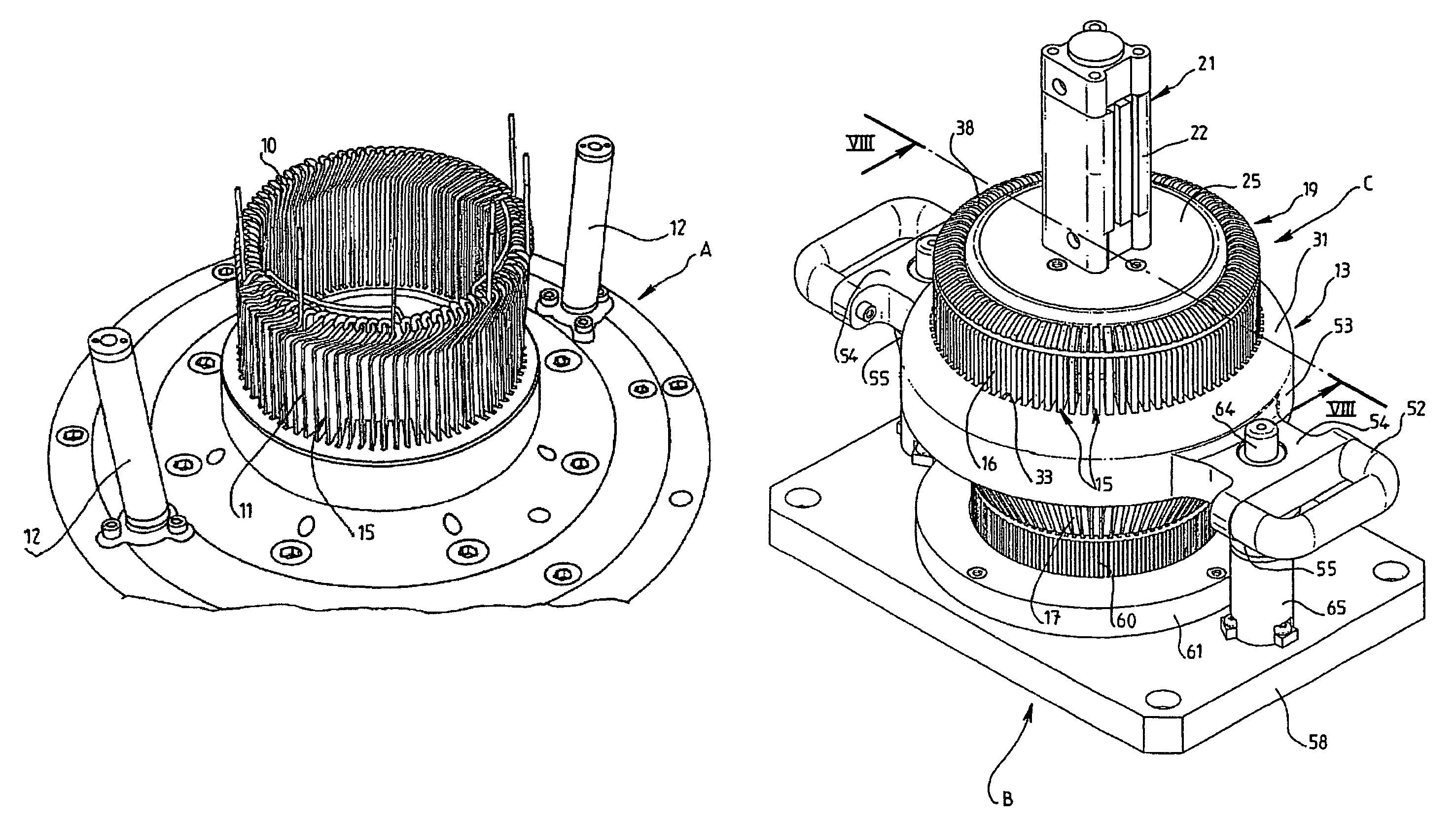
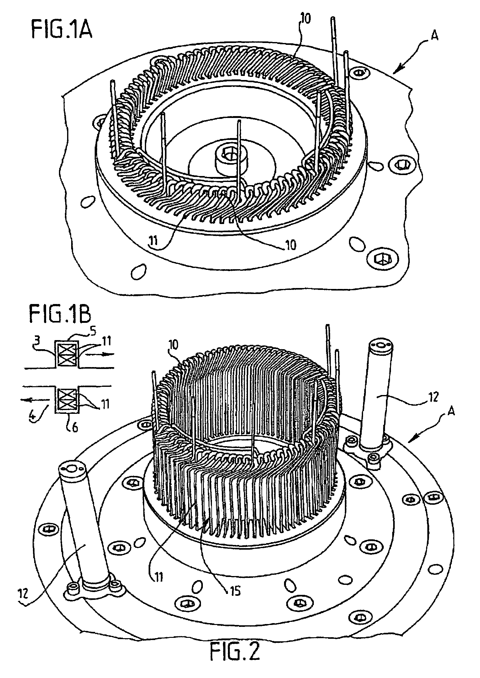
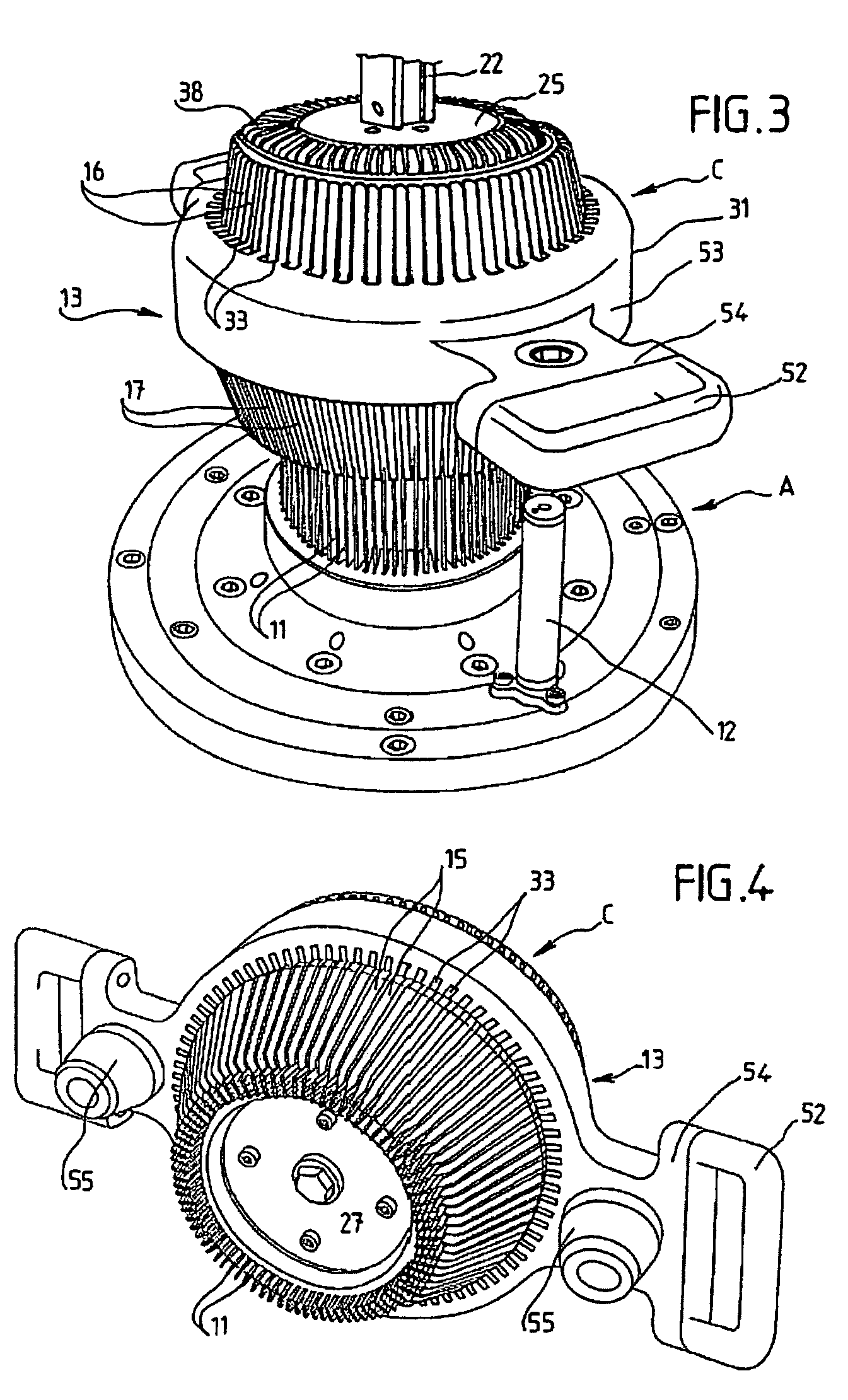
The invention is a system for controlling the movement of levers in a control device. The system includes a cone that can be moved axially in the frame of the control device. The levers are supported on the inclined surface of the cone, and the movement of the cone causes the levers to pivot. This design simplifies the control device and reduces the risk of the levers getting stuck. The levers are also simplified because the control arms have one end in contact with the cone. The system also includes a gripping and transfer device that can be positioned independently of the control device. The gripping and transfer device has marking elements for easy positioning. The system can be used in a predetermined position and includes a separate work station. The positioning mark elements are formed by tubular elements that fit together when the transfer device is placed on the work station. Overall, the system simplifies the control device and improves the movement of the levers.

Problems solved by technology

The disadvantage of this device lies in the fact that it acts on the heads of the pins.
Because of the presence of the case groove, there is a risk that the levers will jam.

Method used


Image

  • Device for gripping and transferring a ring of electrical conductors which is used to produce a winding and a winding-production system employing one such device
  • Device for gripping and transferring a ring of electrical conductors which is used to produce a winding and a winding-production system employing one such device
  • Device for gripping and transferring a ring of electrical conductors which is used to produce a winding and a winding-production system employing one such device

Examples


Embodiment Construction

[0040]The invention will be described in its application to a system for producing a stator of a rotating electrical machine, such as an alternator for an automobile, which is equipped with a bearing annular element in the form of a stator body for mounting a winding formed by many conductors in the form of pins mounted in series. The pins contain two prongs connected by a curved head and are thus generally in the shape of a U. The pins cross with their prongs the body of the stator and form networks called chignons at the two ends of the body of the stator. One of the chignons is formed by the heads of the pins, and the other by the united (by welding, for example) free ends of the prongs of the pins connected to each other according to a specific configuration. The ring-shaped body of the stator is formed, by convention, by a packet of sheets equipped with axial notches for mounting the prongs of the pins.

[0041]The system according to the invention contains a first station A in wh...


PUM

PropertyMeasurementUnit
electricalaaaaaaaaaa
elastically stretchableaaaaaaaaaa
displacementaaaaaaaaaa

Abstract

The invention relates to a device for gripping and transferring a ring of electrical conductors in the form of pins which are used to produce a winding, such as a pin winding. The gripping device (C) is designed to seize the ring from a first element, such as a ring-forming element, and to transfer same into a second element (B), such as an element used to insert the ring into the member that supports the winding to be produced. The inventive device comprises a control cone (19) which can be moved axially inside a frame (13) for contact with levers (15) which are pivot mounted to the frame, such that the levers pivot when the cone is moved. The winding-production system is characterized in that it comprises an autonomous gripping and transfer device (C) which can be separated from the above-mentioned first and second elements (B) and which can be positioned on same in a pre-determined reference position. The invention can be used to produce a stator for an electrically-rotating machine.

Description

BACKGROUND OF INVENTION[0001]1. Field of the Invention[0002]The invention concerns a device for gripping and transferring a ring of electrical conductors in the form of pins, used to produce a winding, such as a pin winding, for the stator of a rotating electrical machine; the gripping device is adapted to seize the ring from a first device, such as a ring-forming element, and transfer it to a second element, such as an element to insert the ring in the element holding the winding to be produced.[0003]The invention also concerns a system for producing a winding on a carrying element, such as the stator with a pin winding of a rotating electrical machine, that includes a ring support element which has axial notches in its internal radially cylindrical face and a winding formed by many electrical conductors, each in the form of a pin that has two prongs connected by a head which are mounted in series, the intermediate straight sections of which are placed in two notches that are angul...

Claims


Application Information

Patent Timeline
Patent Type & Authority Patents(United States)
IPC IPC(8): H02K15/04H02K15/06
CPCH02K15/064Y10T29/49009Y10T29/53143Y10T29/53957Y10T29/53265
Inventor EVEN, DENIS
Owner VALEO EQUIP ELECTRIC MOTEUR
Learn More