Textured laminate flooring

a technology of laminate flooring and textured layers, applied in the field of flooring panels, can solve the problems of adding to or enhancing the aesthetic properties of the flooring panel

Inactive Publication Date: 2007-07-17
COLUMBIA INSURANCE CO
View PDF79 Cites 111 Cited by
  • Summary
  • Abstract
  • Description
  • Claims
  • Application Information

AI Technical Summary

Benefits of technology

[0008]The present invention, in one embodiment, is a decorated floor panel including a core having a top surface and an opposite bottom surface. A decorative layer is adhered to the top surface of the core and, in one embodiment, substantially covers the core. A desired aesthetic appearance, such as a hardwood or ceramic tile appearance, is displayed by the decorative layer of the laminate. Finally, a wear layer is provided over the decorative layer, substantially covering the decorative layer and providing protection from the ambient environment. The wear layer has an exposed wear surface with depressions therein of a variable depth below the wear surface, the depressions being arranged to display a desired texture pattern.
[0010]In yet another aspect, the present invention is a decorated floor panel in which the decorative layer is provided with a decorative pattern. In one embodiment, a plurality of depressions imparted to the wear layer form a desired texture pattern thereon. The relative orientation of the texture pattern and the decorative pattern is controlled such that the depression pattern and the texture pattern are substantially in registration, creating an enhanced, three-dimensional aesthetic appearance to the decorated floor panel.

Problems solved by technology

Thus, while the decorative layer may exhibit an appearance that simulates “natural” flooring materials such as hardwood or ceramic tile, the typical laminate wear layer simply allows an unobstructed view of the laminate decorative layer, and does not add to or enhance the aesthetic properties of the flooring panel.
Further, the location of individual indentations or the “pattern” of indentations provided in prior art systems are unrelated and unlinked to the aesthetic image provided by the decorative laminate layer.

Method used


Image

  • Textured laminate flooring
  • Textured laminate flooring
  • Textured laminate flooring

Examples


Embodiment Construction

[0019]The present invention is more particularly described in the following examples that are intended as illustrative only since numerous modifications and variations therein will be apparent to those skilled in the art. As used in the specification and in the claims, “a,”“an,” or “the” can mean one or more, depending upon the context in which it is used. The preferred embodiment is now described with reference to the figures, in which like numbers indicate like parts throughout the figures.

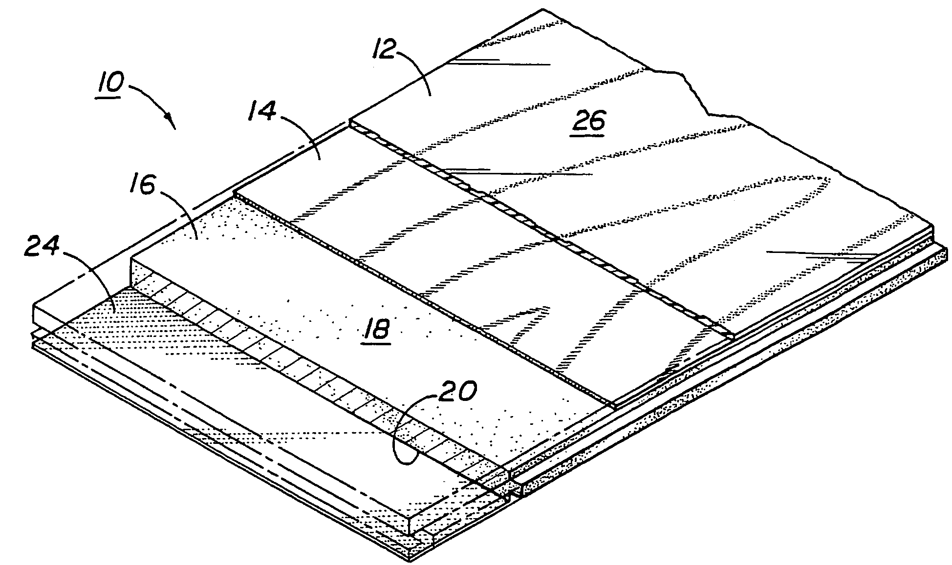
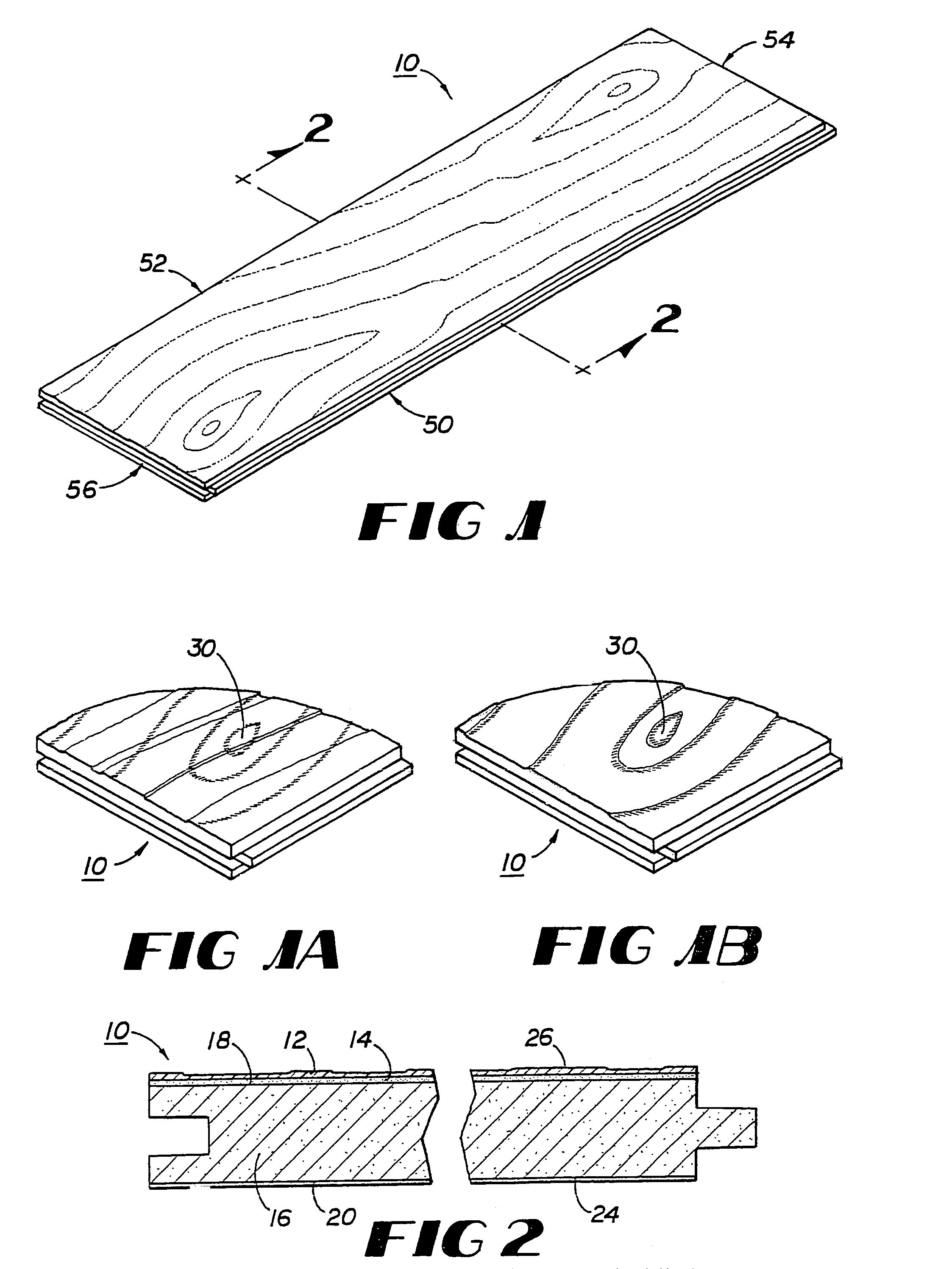
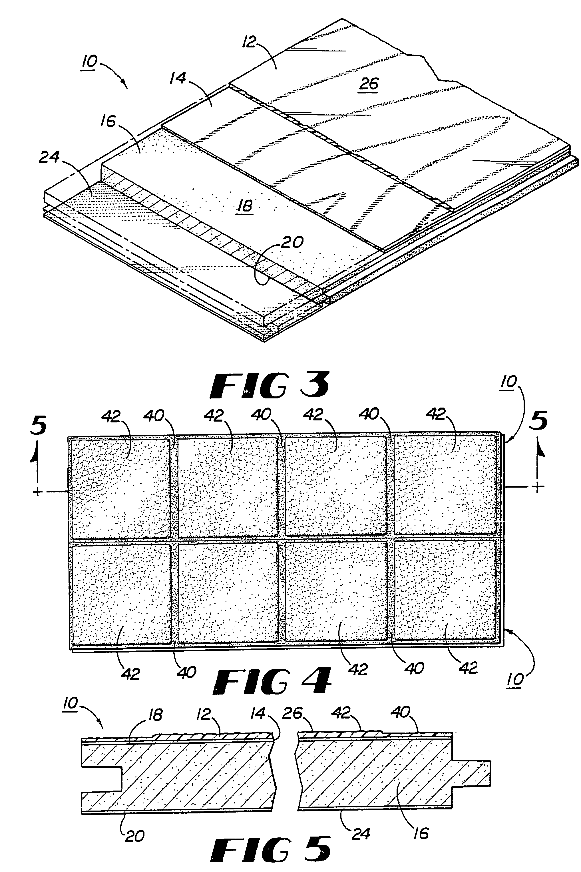
[0020]Referring to FIG. 1, the present invention, in one embodiment, is a decorated floor panel 10. In the illustrated embodiment, the panel 10 is manufactured from a laminated material having a fiberboard core. Alternatively, the floor panel 10 of the invention may be manufactured from other materials, including other laminates such as high pressure laminate (“HPL”), which have been marketed under such trade names as Formica and Pergo. Other materials may also be utilized to construct the floor...


PUM

PropertyMeasurementUnit
depthaaaaaaaaaa
depthaaaaaaaaaa
depthaaaaaaaaaa

Abstract

A decorated floor panel having a core with a top surface and an opposite bottom surface; a decorative layer coupled to the top surface of the core, the decorative layer having a desired aesthetic appearance; and a wear layer coupled to and substantially covering the decorative layer for protecting the decorative layer. The wear layer has an exposed wear surface with depressions therein of a variable depth below the wear surface, the depressions being arranged to display a desired texture pattern. It is noted that this abstract is provided to comply with the rules requiring an abstract that will allow a searcher or other reader to ascertain quickly the subject matter of the technical disclosure. The abstract is submitted with the understanding that it will not be used to interpret or limit the scope or meaning of the claims pursuant to 37 C.F.R. § 1.72(b).

Description

[0001]This application is a continuation of, and claims priority to and the benefit of U.S. patent application Ser. No. 09 / 770,581, entitled “Textured Laminate Flooring,” filed on Jan. 26, 2001 now abandoned, and Ser. No. 10 / 283,002, entitled “Textured Laminate Flooring,” which was filed on Oct. 29, 2002 now abandoned, which are incorporated in its entirety in this document by reference.BACKGROUND OF THE INVENTION[0002]1. Field of the Invention[0003]The present invention relates generally to flooring panels for use in commercial, industrial or residential environments. More particularly, this invention relates to flooring panels having an aesthetically pleasing appearance provided by texturing imparted to the surface of the panels. In certain embodiments, the texture is aligned in registration with a visible graphic design displayed by the panel to further enhance the aesthetic appearance of the flooring panel.[0004]2. Background Art[0005]Various laminates, including high pressure l...

Claims


Application Information

Patent Timeline
Patent Type & Authority Patents(United States)
IPC IPC(8): E04F13/00B32B3/30B44C5/04B44F9/02B44F11/06D21H27/28E04F15/02
CPCB32B3/30B44C5/0469B44C5/0476B44F9/02E04F15/02B44F11/06Y10T428/24355D21H27/28Y10T428/24777B32B21/02B32B2419/00
Inventor MILLER, ROBERT J.BROWNLEE, DAVID M.
Owner COLUMBIA INSURANCE CO
Why Eureka
Try Eureka