
Torque limiting driver with easily disassembled components for sterilization

a technology of limiting driver and components, which is applied in the field of limiting driver, can solve the problems of affecting the cleaning affecting the sterilization effect of the component, and affecting the sterilization effect, etc., and achieves the effect of convenient disassembly and reassembling

Active Publication Date: 2007-07-17
DEPUY PROD INC
View PDF6 Cites 15 Cited by
  • Summary
  • Abstract
  • Description
  • Claims
  • Application Information

AI Technical Summary

Benefits of technology

"The invention is a driver that can be easily disassembled for cleaning and sterilization, and then reassembled. It provides a fixed level of torque in one direction of rotation and can be adjusted by changing the configuration of its components. The driver is designed to be easily handled, reducing the chance of lost components. It is torque-limiting in one direction and non-torque-limiting in the other direction. The driver includes a handle, a shaft component, a cam, and a sleeve. The cam and shaft component work together to provide torque to the shaft component in one direction of rotation and equal or greater torque in the other direction. The driver can be easily disassembled and retained in the handle using a cap."

Problems solved by technology

Particularly, if the component is either over-tightened or under-tightened, there can be associated negative effects.
For example, an under-tightened component may loosen causing the loss of effectiveness of a component, while an over-tightened component may impart an undesirable amount of stress on one or more components.
It is often difficult, however, to ascertain when the proper level of torque has been imparted on an implant component and, in turn, when the implant component has been securely attached.
A problem with these prior art torque-limiting drivers is their complexity and / or their ability to be disassembled for cleaning.
Another problem with these prior art torque-limiting drivers is there lack of being able to be medically sterilized.

Method used


Image

  • Torque limiting driver with easily disassembled components for sterilization
  • Torque limiting driver with easily disassembled components for sterilization
  • Torque limiting driver with easily disassembled components for sterilization

Examples


Embodiment Construction

)

[0035]While the invention is susceptible to various modifications and alternative forms, specific embodiments thereof have been shown by way of example in the drawings and will herein be described in detail. It should be understood, however, that there is no intent to limit the invention to the particular forms disclosed, but on the contrary, the intention is to cover all modifications, equivalents, and alternatives falling within the spirit and scope of the invention.

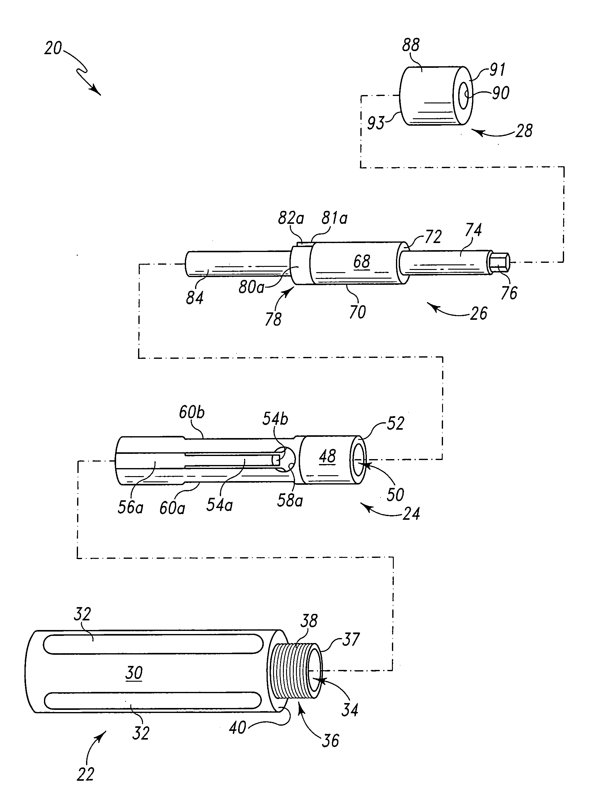
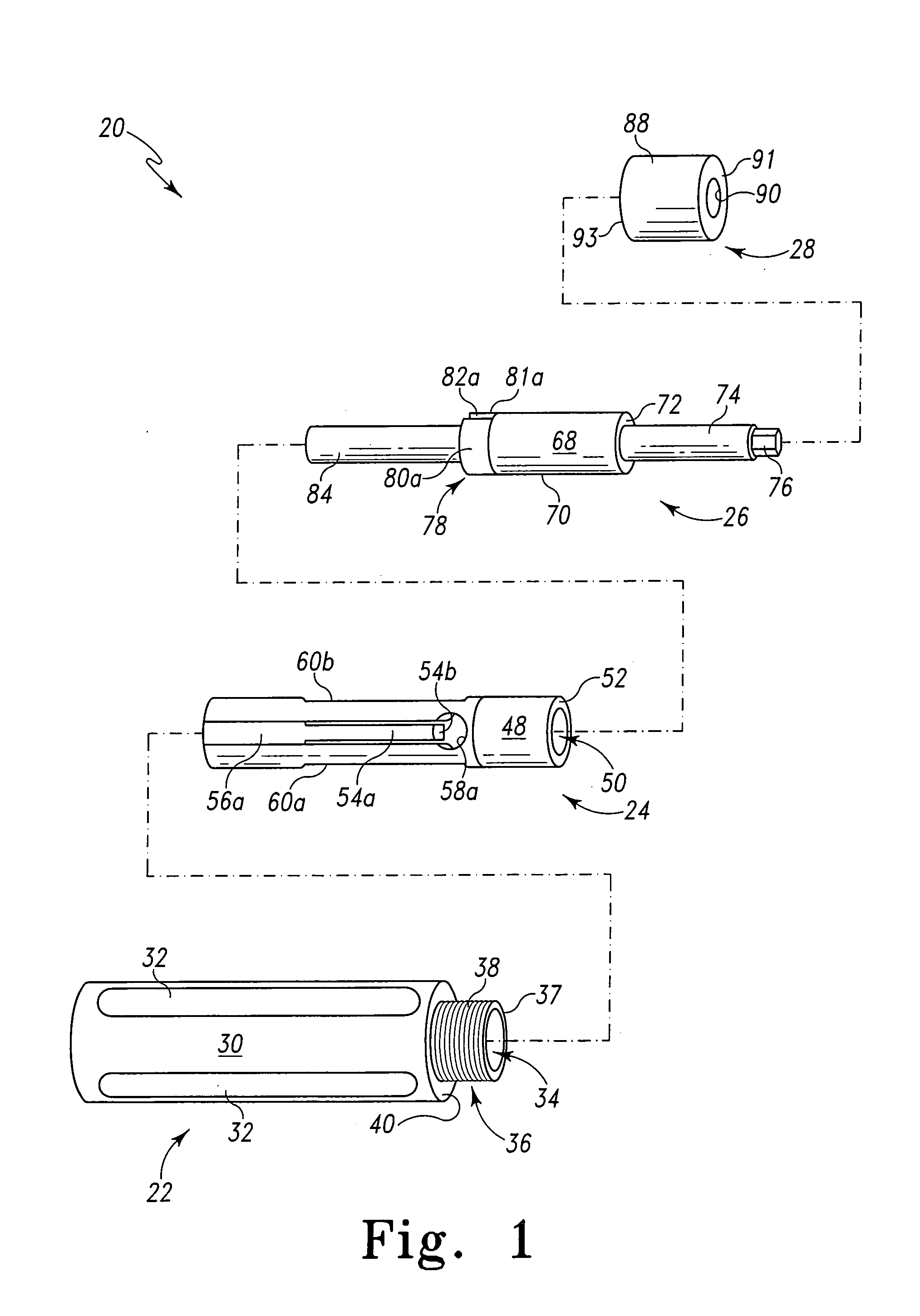
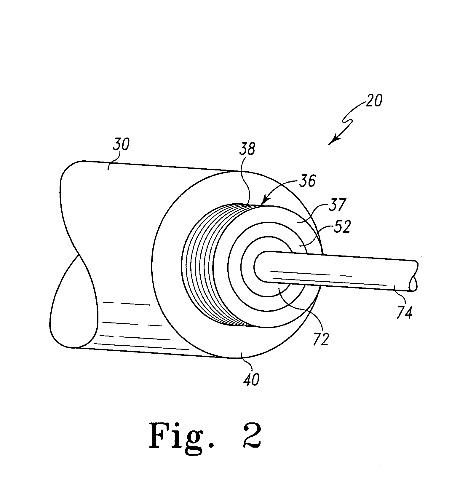
[0036]Referring now to FIG. 1 there is shown an exploded perspective view of an exemplary torque-limiting driver, generally designated 20, in accordance with the principles of the subject invention. In the exemplary form, the driver 20 includes a handle or handle component 22, a sleeve or sleeve component 24, a shaft or shaft component 26 and an end cap 28. As represented by the arrows, the handle component 22 receives the sleeve component 24, the sleeve component 24 receives the shaft component 26, and the end cap 28...


PUM


Abstract

A driver has components that are easily disassembled for cleaning and / or sterilization. Once disassembled, the limited number of components allows for easy reassembly. The driver utilizes a cam that rides on spring fingers for determining the level of producible torque that the driver can produce. The cam and spring fingers are contained in a housing. Particularly, the spring fingers are part of a finger housing that is key lockable with the housing when assembled for movement as one unit. The cam is integral with a driver shaft and is received within the finger housing. The cam and driver shaft are limitedly rotatable with respect to the finger housing. The level of producible torque may be changed by providing cams and / or spring fingers of various dimensions. The driver is torque-limiting in one direction (tightening) and essentially non torque-limiting in the opposite direction (loosening). The various components are also large enough to be easily handled reducing the chance of lost components.

Description

BACKGROUND[0001]1. Field of the Invention[0002]The present invention relates to devices for applying a particular level of torque to an orthopedic implant component and, more particularly, to a torque limiting driver for applying a particular level of torque to an orthopedic implant component that can be easily disassembled for sterilization of the torque limiting driver components.[0003]2. Background Information[0004]Various types of orthopedic implants such as spine implants and joint prosthetics typically utilize and / or rely on components that must be securely attached to other components of the implant or to various parts of the body. The integrity and / or effectiveness of the implant may depend upon proper attachment of the component. Particularly, if the component is either over-tightened or under-tightened, there can be associated negative effects. For example, an under-tightened component may loosen causing the loss of effectiveness of a component, while an over-tightened com...

Claims


Application Information

Patent Timeline
Patent Type & Authority Patents(United States)
IPC IPC(8): B25B23/14A61B17/88A61B19/00A61H1/00
CPCA61B17/8875B25B23/141B25B23/1427A61B2019/301A61B2019/4868A61B2090/031A61B2090/0813
Inventor FRAZEE, EDMUND W.
Owner DEPUY PROD INC
Learn More