Spacer expander

a technology of expander and expansion plate, which is applied in the direction of brake system, machine/engine, transportation and packaging, etc., can solve the problems of difficult control of the amount of axial movement of the outer peripheral portion of the upper and lower rails in the cylinder, limit in reducing the combined axial width, and difficult to reduce the axial width of the connecting portion, etc., to achieve excellent fit and stability, reduce the axial width of the combined oil ring, and improve the fuel efficiency of the engin

Inactive Publication Date: 2007-07-17
RIKEN CO LTD
View PDF9 Cites 15 Cited by
  • Summary
  • Abstract
  • Description
  • Claims
  • Application Information

AI Technical Summary

Benefits of technology

[0014]The present invention provides a spacer expander of a combined oil ring that comprises a spacer expander and a pair of side rails supported by the spacer expander, and the axial width of the combined oil ring can be reduced. The spacer expander of the present invention is made of a flat strip of metal. Protruding portions in the axial direction of a piston are formed in the inner peripheral portion of the spacer expander as to press side rails outward in the radial direction, outer peripheral portions that are adjacent to the protruding portions in the inner peripheral portion (inner peripheral protruding portions) are cut off, and protruding portions are formed in the outer peripheral portion that are adjacent to the cut off portions (slits) as to support side rails in the axial direction.
[0016]A spacer expander of the present invention is made of a metal strip, and a wave-shaped profile in the axial direction of inner peripheral side ear portions (inner peripheral protruding portions) provides tension. Therefore, there is no need to form a wave-shaped profile on the outer peripheral side for controlling tension as in the conventional way. Thus, the combined axial width is equal to the sum of the axial widths of upper and lower side rails and the thickness of the metal strip that forms the spacer expander, or the width of the outer peripheral portion of the spacer expander. Therefore, compared with the case using a spacer expander of a conventional configuration, the axial width of the combined oil ring can be greatly reduced. As a result, a smaller and lighter piston can be obtained, and better fuel efficiency of engines can be realized. In addition, the connecting portion extending toward the outer peripheral side provides an excellent fit and stability. Also, by forming upper and lower supporting portions on the space expander for supporting side rails, a more excellent stability and followability can be obtained.

Problems solved by technology

However, for conventional spacer expanders, wave shapes have been manufactured by gear machining, and thus it has been difficult to reduce the axial width of the connecting portion due to manufacturing reasons.
Therefore, there has been a limit in reducing the combined axial width.
Therefore, it is difficult to control the amount of axial movement of the outer peripheral portion of the upper and lower rails in the cylinder.
This may inhibit the reduction of oil consumption by the width reduction, and may cause unusual noises.
Also, the tension of the spacer expander needs to be controlled by the width and number of slits that are formed alternately on the outer peripheral side and the inner peripheral side, and thus, machining process becomes complicated and restricted.
In addition, reduction in width and weight is limited due to the thickness and weight of the shape steel material itself.

Method used


Image

  • Spacer expander
  • Spacer expander
  • Spacer expander

Examples


Embodiment Construction

[0044]Referring to the drawings, preferred embodiments for implementing the present invention are described below.

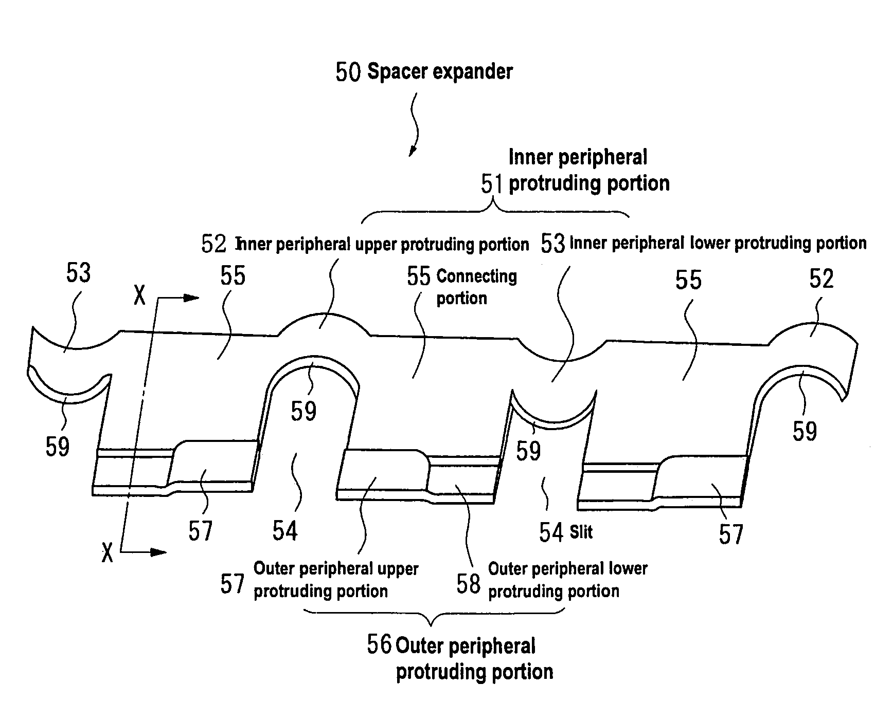
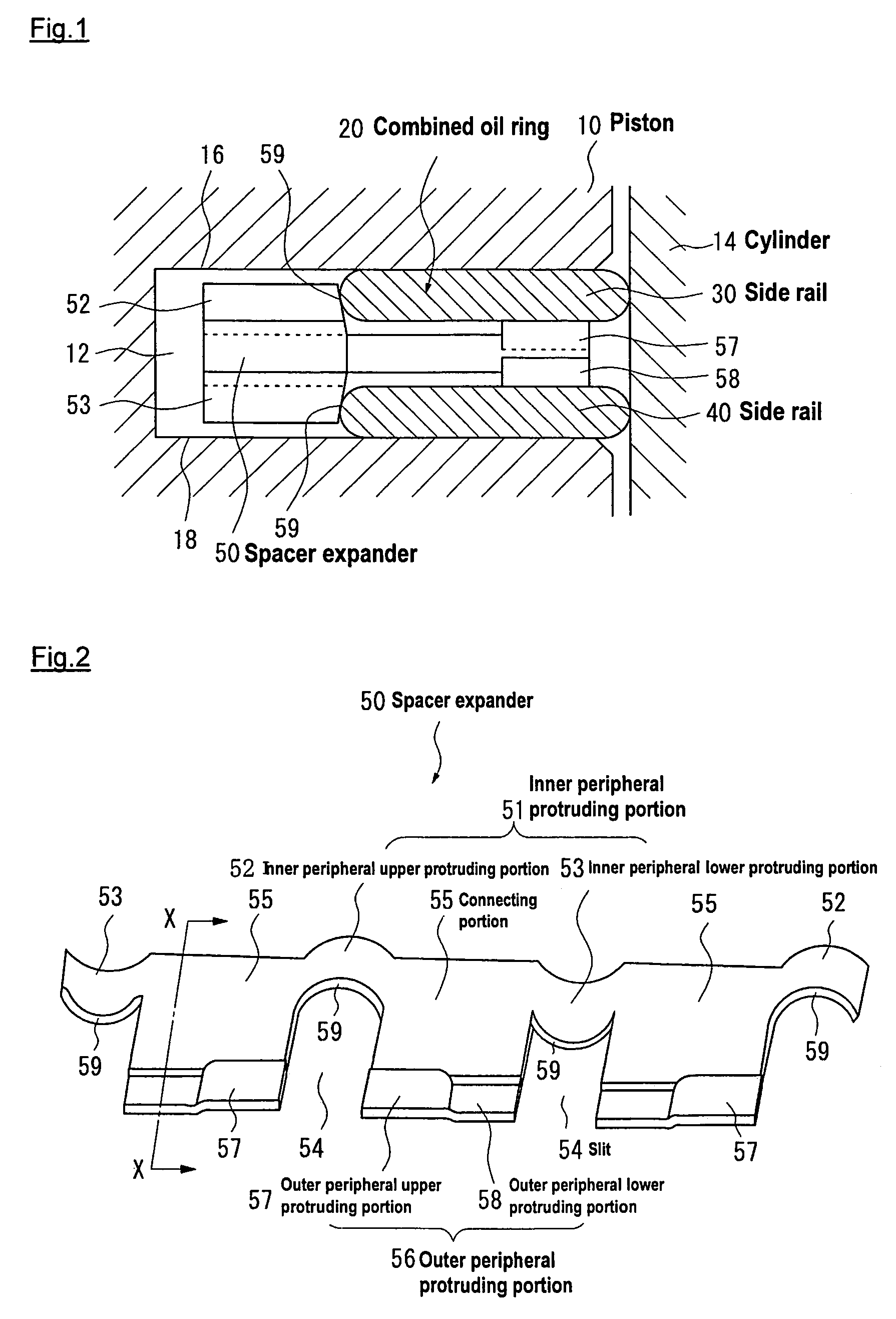
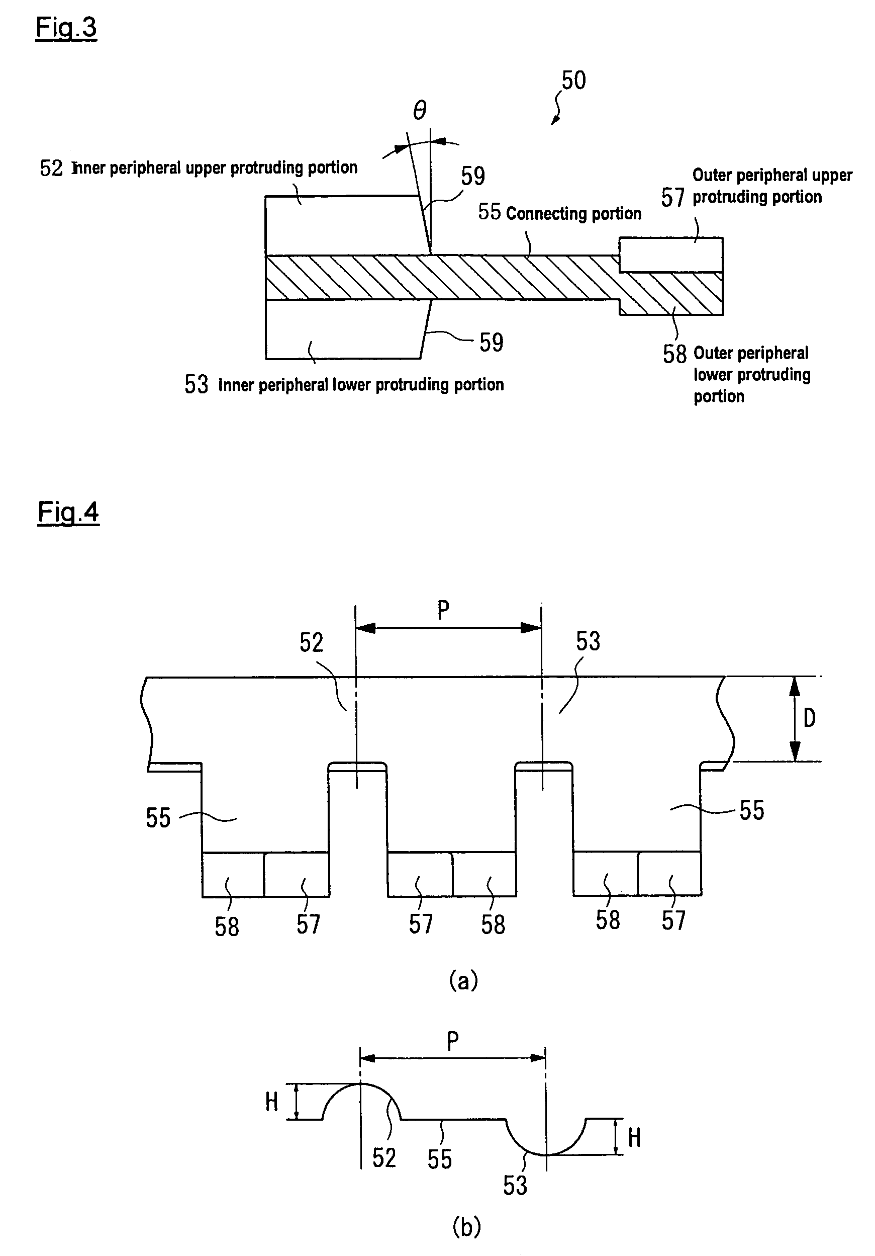
[0045]FIG. 1 is a cross sectional view showing a configuration of a three-piece type combined oil ring according to the present invention. FIG. 2 is an enlarged perspective view of a part of a spacer expander. FIG. 3 is a vertical cross sectional view of a spacer expander, taken along line X-X of FIG. 2. In FIG. 1, an oil ring 20 is installed in an oil ring groove 12 of a piston 10 for oil sealing and oil controlling.

[0046]When the combined oil ring 20 is installed in the oil ring groove 12 of the piston 10, outer peripheral surfaces of a pair of side rails 30 and 40 contact with the inner peripheral surface of a cylinder 14 at a certain contact pressure.

[0047]As shown in FIG. 2, a spacer expander 50 is made of a metal strip and has a plurality of inner peripheral protruding portions 51 that protrude in the axial direction of the piston (hereafter, axial direction) on th...


PUM


Abstract

In a combined oil ring having a spacer expander to be installed between a pair of upper and lower side rails, a plurality of axially protruding inner peripheral protruding portions are formed on the inner peripheral side of the spacer expander along its peripheral direction. The inner peripheral protruding portions press the inner peripheral surface of the side rails. On the outer peripheral side of the spacer expander, a plurality of slits are formed, and a plurality of connecting portions are located in the peripheral direction isolated by the slits. On the plurality of connecting portions, axially protruding outer peripheral protruding portions are formed.

Description

[0001]This application is a continuation of PCT Application No. PCT / JP2004 / 11749, which was filed Aug. 16, 2004 and designated the United States, which claims priority to Japanese Patent Application No. 2003-297108, which was filed on Aug. 21, 2003, both of which are incorporated herein by reference.TECHNICAL FIELD[0002]This invention relates to a spacer expander of a three-piece type combined oil ring that is installed in a piston of an internal combustion engine and performs oil controlling.BACKGROUND[0003]A cross sectional configuration of general piston rings installed in a piston of an internal combustion engine is shown in FIG. 9. In a piston 100, ring grooves 110, 120, and 130 are formed for accommodating piston rings. In each ring groove, compression rings 200 and 210 are mainly for gas sealing, and a three-piece oil ring 220 is mainly for oil controlling and oil sealing are inserted respectively. In accordance with the reciprocating motion of the piston 100, outer periphera...

Claims


Application Information

Patent Timeline
Patent Type & Authority Patents(United States)
IPC IPC(8): F16J9/20F16J9/06F02F5/00
CPCF16J9/068F16J9/06
Inventor USUI, MIYUKIKATAYAMA, NOBUONAKAZAWA, MASAHIRO
Owner RIKEN CO LTD
Why Eureka
Try Eureka