Positioning device for adjustable housing

a technology of holding device and adjustable housing, which is applied in the direction of bumpers, pedestrian/occupant safety arrangements, instruments, etc., can solve the problems of complex and expensive tools that are required in the system described above, and achieve the effects of simple design, easy manufacturing, and convenient form

Inactive Publication Date: 2007-07-17
ROBERT BOSCH GMBH
View PDF14 Cites 6 Cited by
  • Summary
  • Abstract
  • Description
  • Claims
  • Application Information

AI Technical Summary

Benefits of technology

[0009]For optimum adjustment in horizontal and vertical directions, the housing may be mounted at the mounting location or on the intermediate holder using three adjusting screws, which, in an exemplary embodiment, are held on the housing in blind rivets into which the adjusting screws may be driven with their threads in a self-locking manner. Thus, the holding torque required for the screws may be easily accomplished because the blind rivets are self-locking or self-securing to a sufficient degree to prevent maladjustment.
[0011]The holding device according to an exemplary embodiment of the present invention has the advantage that it is possible to use plastic domes which are easy to manufacture and which may be directly attached, for example, to the front end of a motor vehicle or to an intermediate holder having a relatively simple design. The plastic domes may be latched and secured at the mounting location with a geometry that is easy to form, providing a rotatable support including the tilting of the adjusting screws which, in some holding devices, could only be achieved by an expensive ball socket.
[0012]Thus, the holding device according to an exemplary embodiment of the present invention is relatively inexpensive to implement and may be easily adapted to the specific mounting situation in a flexible manner.

Problems solved by technology

The difficulty is to find an installation space for the radar sensor which, on one hand, offers enough space and meets the high-frequency requirements and, on the other hand, allows simple and thus inexpensive adjustment of the radar sensor at the end of the manufacturing process.
Some systems described above require very complex and expensive tools, because, in each case, a punching and bending tool and a tool for coating the holding device with plastic are required.

Method used


Image

  • Positioning device for adjustable housing
  • Positioning device for adjustable housing
  • Positioning device for adjustable housing

Examples


Embodiment Construction

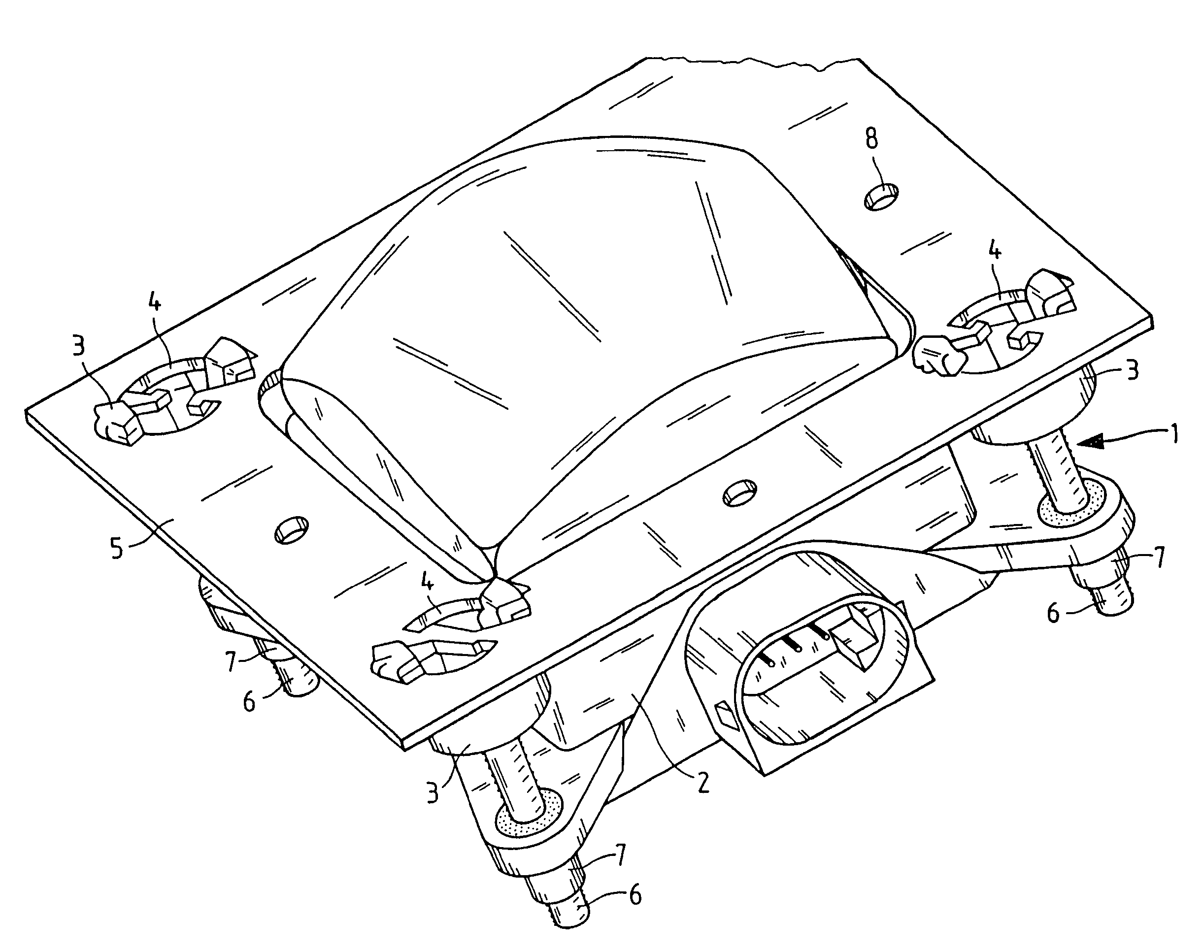
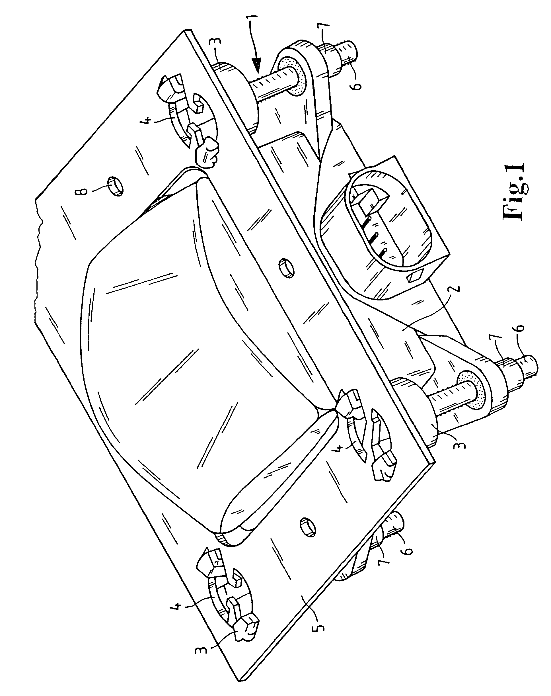
[0020]FIG. 1 shows a perspective view of a holding device 1 for a distance sensor 2 which is designed as a radar sensor. For attachment at a suitable mounting location on a motor vehicle, distance sensor 2 is adjustably attached, for example, to the front bumper by holding device 1.

[0021]Here, three plastic domes 3 are provided as connecting elements of holding device 1, the plastic domes being clipped into the corresponding openings 4 at the mounting location of the component of the motor vehicle or, as shown here, at an intermediate holder 5. Adjusting screws 6, which are provided with a ball head, are pressed into plastic domes 3. Adjusting screws 6 are mechanically connected to the housing of sensor 2 via blind rivets 7, adjusting screws 6 being secured in the respective blind rivet 7 by the self-locking action of the thread.

[0022]To adjust sensor 2 at the mounting location using holding device 1, a rotation of adjusting screws 6 and, thereby, a suitable horizontal and vertical ...


PUM


Abstract

A holding device for an adjustable housing, such as the housing of a radar sensor, which allows the position of the housing at a mounting location to be changed in at least one degree of freedom using least one adjusting screw. In this context, the at least one adjusting screw is held at the mounting location in a fixing dome so that it can be rotated and tilted, the respective fixing dome of plastic being capable of being snapped into a corresponding opening at the mounting location so that it is secured against rotation and pulling.

Description

FIELD OF THE INVENTION[0001]The present invention relates to a holding device for an adjustable housing, e.g., for the housing of a radar sensor, where the housing may be mounted on the outside of a motor vehicle.BACKGROUND INFORMATION[0002]Such a radar sensor may be screwed to a vehicle on the outside with a holding device. This radar sensor may be, for example, a component of a proximity warning system or ranging system, which continuously processes information on the distance and / or the relative speed of the vehicle with respect to other vehicles and the road conditions. In this context, the radar sensor may be very accurately aligned with the longitudinal vehicle axis, as a result of which the sensor may be adjusted in horizontal and vertical directions upon installation into the vehicle, because of the sometimes considerable vehicle tolerances in the region of the mounting location.[0003]German Patent Application 199 24 055, for example, refers to adjusting the radar sensor fro...

Claims


Application Information

Patent Timeline
Patent Type & Authority Patents(United States)
IPC IPC(8): F16M11/24B60R21/00B60R19/48F16B5/02F16B21/04G01S7/03G01S7/40G01S13/931
CPCB60R19/483G01S7/02G01S13/931G01S7/4026G01S2013/9371G01S2013/9389G01S2007/027G01S2007/4034G01S2007/403G01S2013/9375G01S2013/9327G01S2013/93275G01S2013/93271G01S7/4034G01S7/403G01S7/027
Inventor ZEIHER, JUERGENKLAAS, THOMASKOERBER, SABINEREICHERT, ANDREAS
Owner ROBERT BOSCH GMBH
Why Eureka
Try Eureka