

Thread guidance device for a textile machine, in particular for a ring spinning machine
A technology of guiding device and textile machine, which is applied in the direction of textiles and papermaking, and can solve the problems that the spinning machine is not feasible
- Summary
- Abstract
- Description
- Claims
- Application Information
AI Technical Summary
Problems solved by technology
Method used
Image

Examples
Embodiment Construction
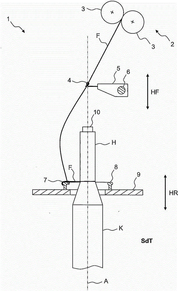
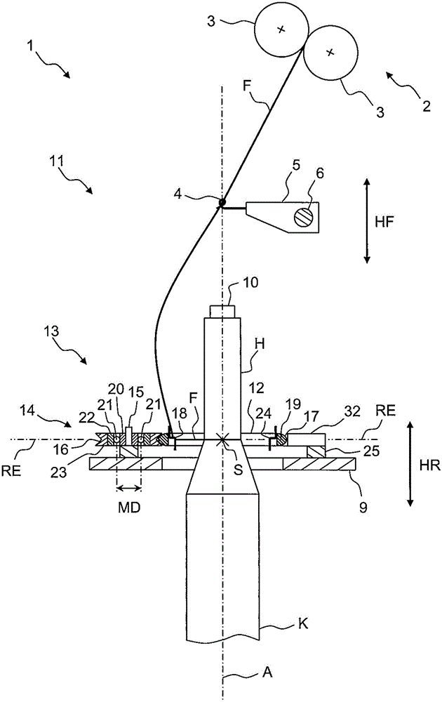
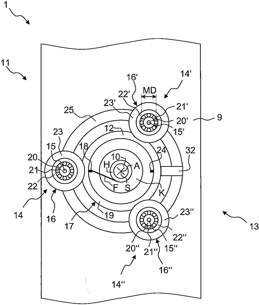
[0061] figure 1 An exemplary embodiment of a spinning table 1 of a conventional ring spinning machine is shown in a schematic side view. In practice, the ring spinning machine has a plurality of such spinning stands which are arranged one behind the other in the plane of the illustration.
[0062] The spinning stand 1 has a stretching device 2 of which only one delivery roller pair 3 is shown. The drawing device serves to modify the conveyed roving and to provide it as yarn F in the desired fineness. The yarn F exits straight from the drawing device 2 through the yarn guide hole 4 which is fixed via the holder 5 to the yarn guide platform 6 above the spinning stands 1 extend. The yarn F runs in an arc along the yarn guide hole 4 downstream to the moving part 7, which is hung on the ring 8, which is fixed on one side thereof to an annular platform 9, which is placed on the The plurality of spinning stands 1 extend above. The movement 7 reverses the yarn F so that it runs t...
PUM
| Property | Measurement | Unit |
|---|---|---|
| Diameter | aaaaa | aaaaa |
Abstract
Description
Claims
Application Information