
Underwater pool light

a technology for pool lights and underwater pools, which is applied in the direction of lighting applications, lighting heating/cooling arrangements, and coupling device connections, etc., can solve the problems of no pool light presently available, cost of repairing or replacing shutters, and inability to adjust the distance of conventional pool lights

Inactive Publication Date: 2007-07-17
AQUA PHAROS INT
View PDF14 Cites 13 Cited by
  • Summary
  • Abstract
  • Description
  • Claims
  • Application Information

AI Technical Summary

Benefits of technology

[0034]Preferably the lens includes fastener locating means and a fastener for fastening the lens to the lens holding member. Preferably the fastener locating means comprises a hollow coned protrusion for aligning the lens to a fastener receiving aperture provided at the lens holding member. The cammed members and fastener locating means allow self alignment of the lens to the lens holding member.
[0035]Preferably the housing includes a lamp enclosure which is sealably connected to the lens by a plurality of fasteners. Preferably the housing includes a trim guard which covers the fasteners to prevent unfastening of the fasteners. Preferably the trim guard includes a plurality of pegs which are received in apertures provided at the lens. The trim guard prevents removal of the lens for replacement of the bulb or other maintenance of the pool light.

Problems solved by technology

For steel shutters, which are typically hired from a supplier, the cost of repairing or replacing the shutter is incurred.
It is a difficult task, given this variation in thickness, for the pool builder to ensure that the finishers are flush against the flange member of the niche.
The same problem exists for the pool builder when applying the finishers to ensure they are flush with the flange member of each niche.
Conventional pool lights do not offer a means for adjusting the distance from visible parts of the pool light, such as the flange member, to the wall of the pool to accommodate variation in thickness of the finishers.
Furthermore, no pool light presently exists which can be fitted to each of the four types of pools described above without modification by the pool builder.
However, there is limited ability for water to flow within the niche.
This can cause the accumulation of body fat from swimmers, which can be a health hazard as it encourages the growth of bacteria such as legionella.
Removal of the housing typically requires the removal of a number of screws, which is a difficult task to carry out underwater, due to a lack of visibility and mobility.
Conventional pool lights do not provide this wet mateable connection or suitable fittings.
Also, the male connectors often include a guide pin which is easily damaged.
It is undesirable and inefficient for the projected light to be projected upwards relative to the base of the pool.
Also, the angle of illumination, in the plane of the base of the pool, is limited.

Method used


Image

  • Underwater pool light
  • Underwater pool light
  • Underwater pool light

Examples


Embodiment Construction

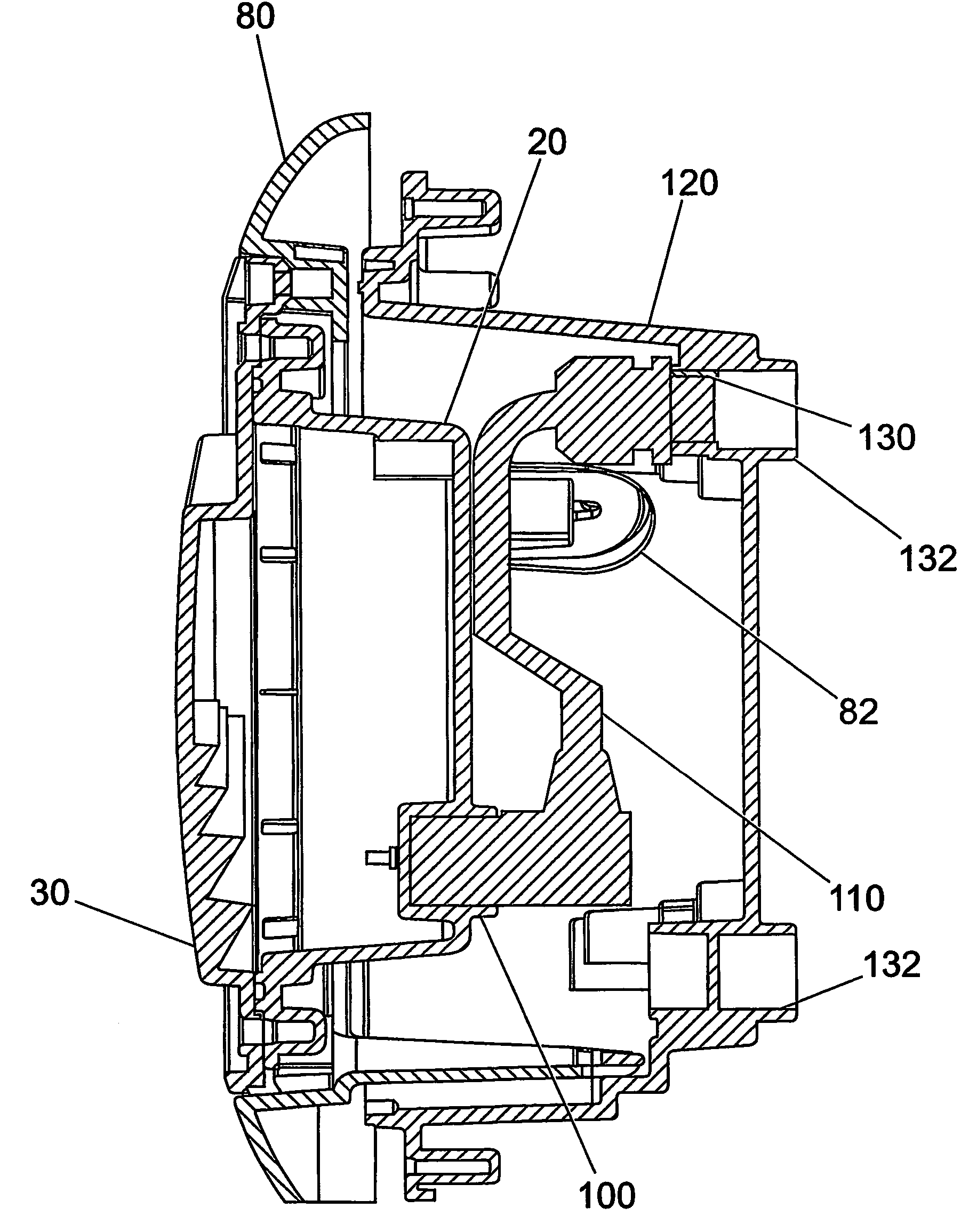
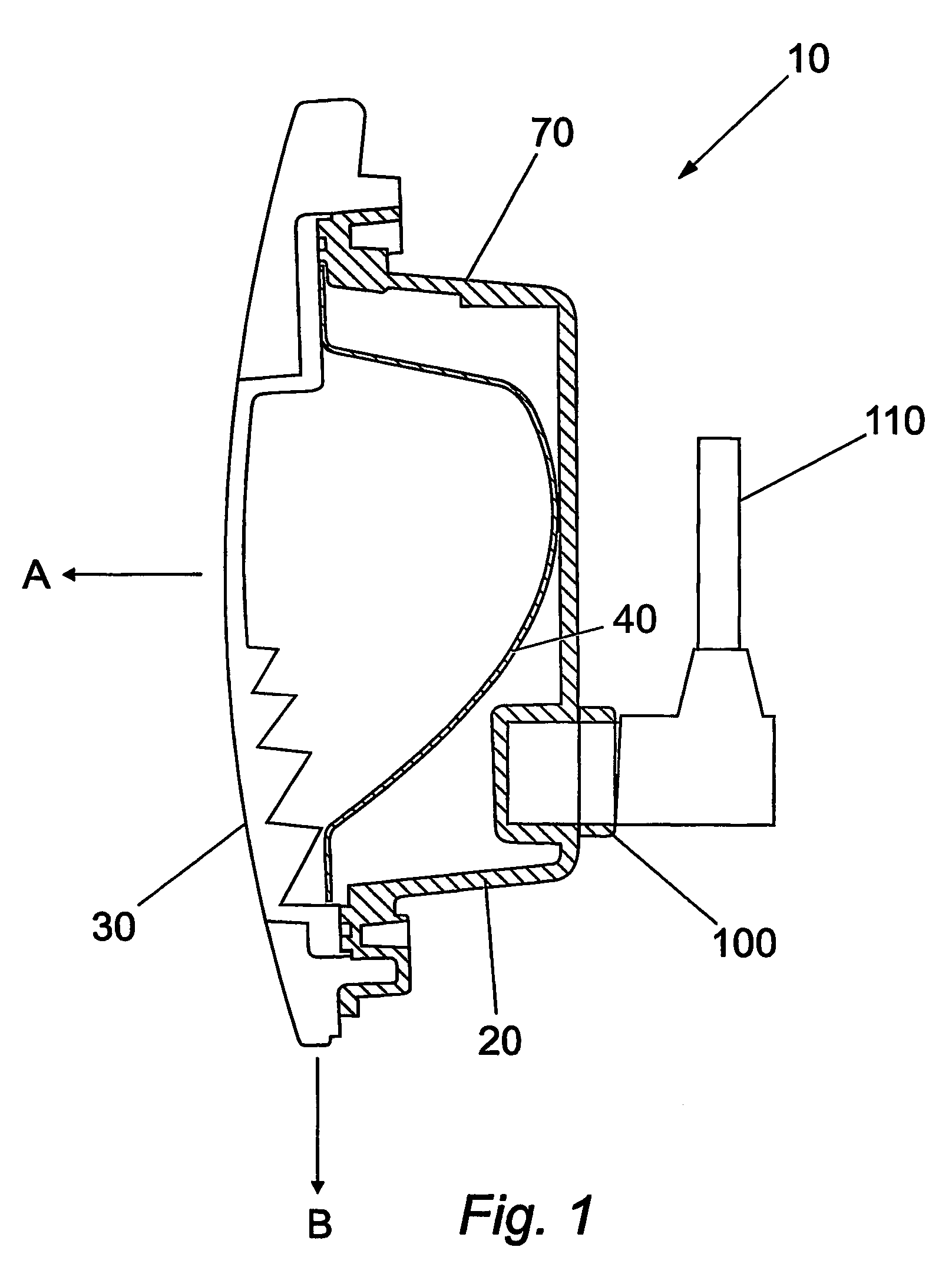
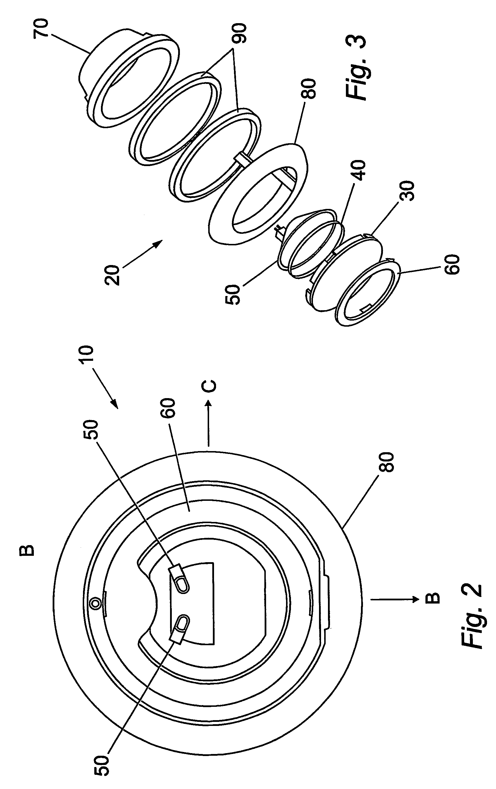
[0069]Referring to FIGS. 1 to 3 there is shown a pool light 10 comprising a housing 20 which has a opening that is covered by a lens 30. A reflector 40 and a light source in the form of two bulbs 50 are housed within the housing 20. A trim guard 60 is fitted to the lens 30.

[0070]The housing includes a lamp enclosure 70 and lens holding member, or bezel 80, which is sealably connected to the lamp enclosure 70 using a number of gaskets 90.

[0071]A collar (not shown) may be provided as projecting from the inner circumference of the lamp enclosure 70. This collar, typically of 50 millimetres length, provides an edge up to which a pool builder may apply finishers to the pool wall. Once the finishers had been applied, the collar may then be trimmed so that its projecting edge is flush with the pool wall.

[0072]The lamp enclosure 70 includes an electrical connector 100 for connection to a power supply cable 110. Internal wiring (not shown) connects the connector 100 to the two bulbs 50.

[0073...


PUM


Abstract

An underwater pool light comprises: a housing; a lens sealingly fixed to the housing; a light source located within the housing; and mounting means for mounting the housing to a niche within or on a wall of a pool. The housing includes an integral connector for external connection to an electrical supply cable, and the pool light includes electrical connection means within the housing connecting the light source to the integral connector.

Description

[0001]This Application is the U.S. National Phase Application of PCT International Application No PCT / GB2003 / 005305 filed Dec. 10, 2003.[0002]The present invention relates to an underwater pool light. In particular, but not exclusively, the invention relates to disposable underwater pool lights for use in swimming pools and spa baths, hereafter referred to as “pools”.DESCRIPTION OF THE RELATED ART[0003]Pools are conventionally built in one of four manners. The first method is to provide two spaced shutters formed from wood or steel, with steel reinforcing bars arranged between the shutters. Apertures are provided at a number of locations in one of the shutters and a niche for the pool light is located in each of the apertures. Typically, the niche is positioned such that a gap exists between the shutter and a flange member provided on the niche. Typically, conventional niches have to be modified so that they are fixed to the shutter by fastening, usually by screwing, a portion of th...

Claims


Application Information

Patent Timeline
Patent Type & Authority Patents(United States)
IPC IPC(8): F21V31/00F21S8/00F21V5/04F21V11/16F21V23/06H01R13/523
CPCF21S8/00F21V23/06H01R13/523F21V5/045F21V11/16F21W2131/401
Inventor POGGI, BRIAN
Owner AQUA PHAROS INT
Learn More