
Cleaning apparatus for vehicle lamp

a technology for cleaning apparatus and vehicle lamps, which is applied in the direction of vehicle cleaning, roof cleaning, cleaning using liquids, etc., can solve the problems of damage to the connecting portion between the nozzle cover and the nozzle portion, and the nozzle cover may be unfastened, so as to prevent the unfastening or the like of the nozzle cover from a nozzle portion

Inactive Publication Date: 2012-04-10
KOITO MFG CO LTD
View PDF6 Cites 0 Cited by
  • Summary
  • Abstract
  • Description
  • Claims
  • Application Information

AI Technical Summary

Benefits of technology

[0010]One or more embodiments of the invention provide a cleaning apparatus for vehicle lamp in which unfastening or the like of a nozzle cover from a nozzle portion is prevented.
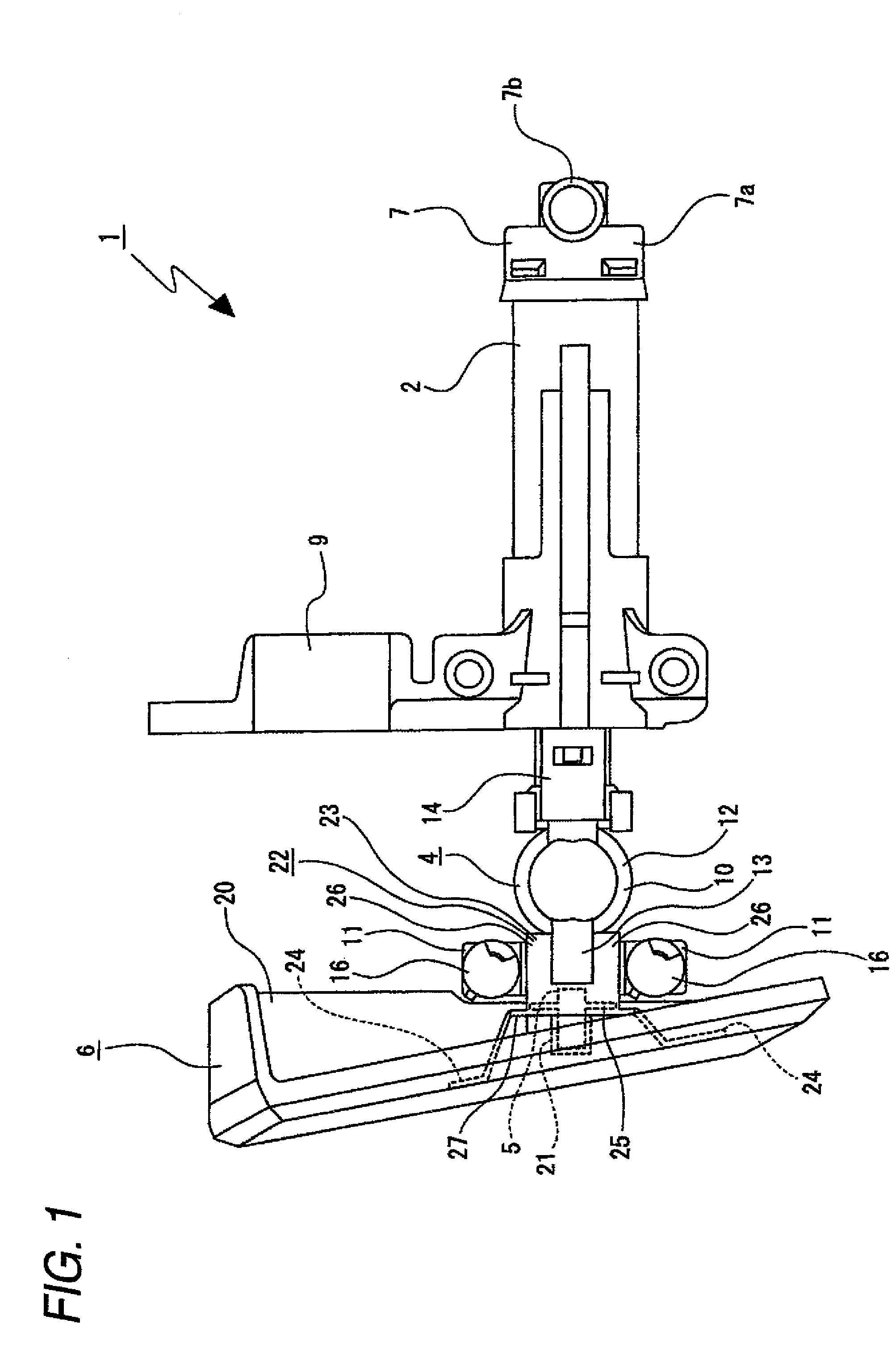
[0013]Even when the force in the direction in which the nozzle cover is inclined with respect to the movement direction is applied to the nozzle cover, the nozzle cover moves to the movement direction without being inclined, and an unfastening or a damaging of the nozzle cover can be prevented.
[0014]Further, the nozzle cover may have a shape which is long in one direction, and the arm portion may include a pair of arms which are spaced apart from each other in a longitudinal direction of the nozzle cover. Thereby, the inclination of the nozzle cover particularly in the direction in which the nozzle cover tends to be inclined with respect to the movement direction can be prevented.
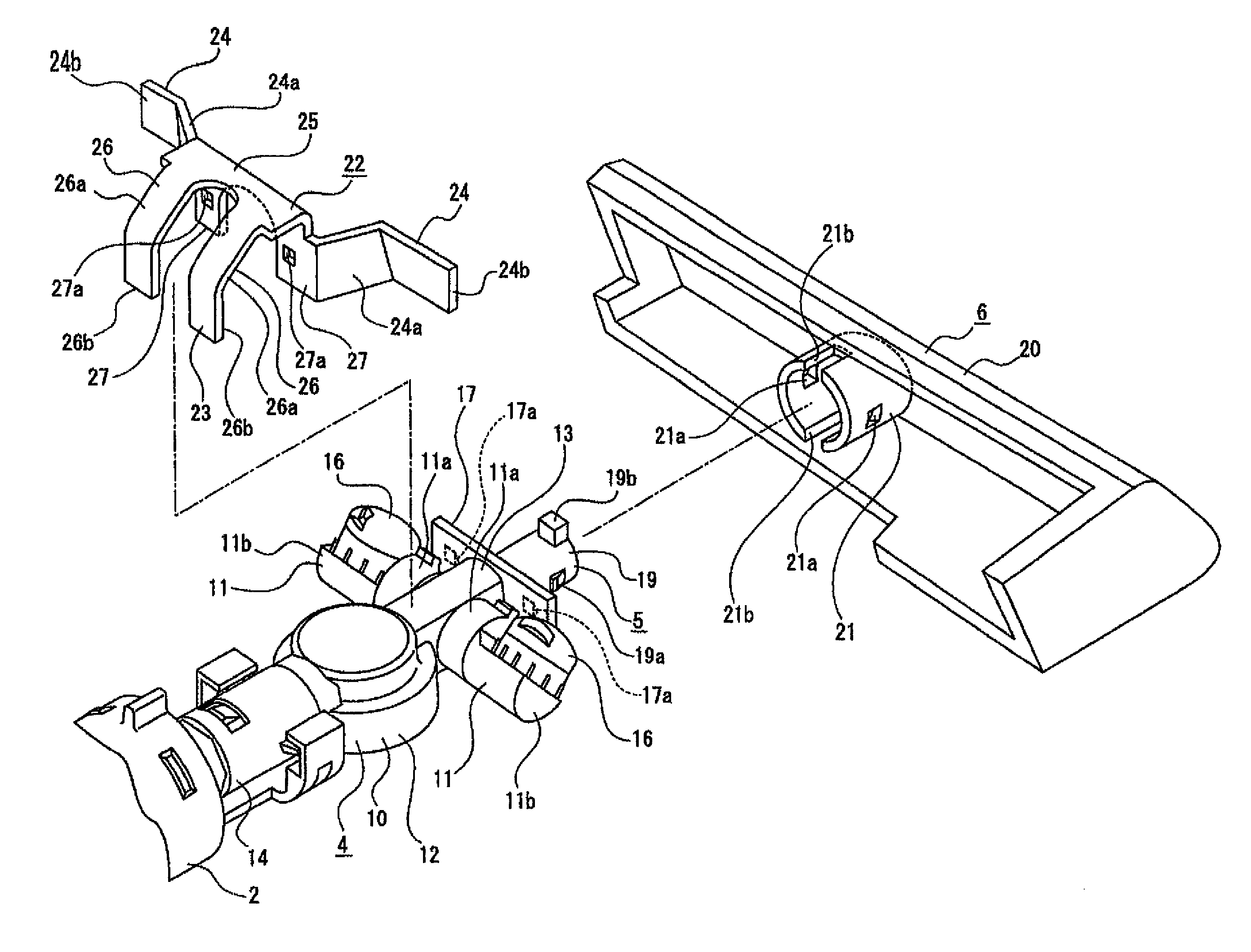
[0015]Further, the cleaning apparatus may include a holder provided between the nozzle cover and the nozzle portion for connecting the nozzle cover and the nozzle portion and integrally movable with the piston in the movement direction, and a leg portion that is provided in the bracket and regulates an inclination of the holder with respect to the movement direction. Thereby, the unfastening of the holder from the nozzle portion or the damage thereof can be prevented.
[0016]Moreover, the cleaning apparatus may include: a cylindrical portion that is provided in the nozzle portion, extends in a direction orthogonal to the movement direction, and supports the jet nozzles; a plate portion that is provided on the holder and extends in the direction orthogonal to the movement direction, and a cylindrical portion holding portion and a plate portion holding portion that are provided in the bracket and pinch the cylindrical portion and the plate portion therebetween. Thereby, the unfastening of the holder from the nozzle portion can be prevented, and the bracket can be easily and firmly attached to the holder and the nozzle portion.

Problems solved by technology

As a result, there is a possibility that the nozzle cover may be unfastened from the nozzle portion, or the connecting portion between the nozzle cover and the nozzle portion may be damaged.

Method used


Image

  • Cleaning apparatus for vehicle lamp
  • Cleaning apparatus for vehicle lamp
  • Cleaning apparatus for vehicle lamp

Examples


Embodiment Construction

[0024]Hereinafter, an exemplary embodiment of a cleaning apparatus for a vehicle lamp of the invention will be described with reference to the accompanying drawings.

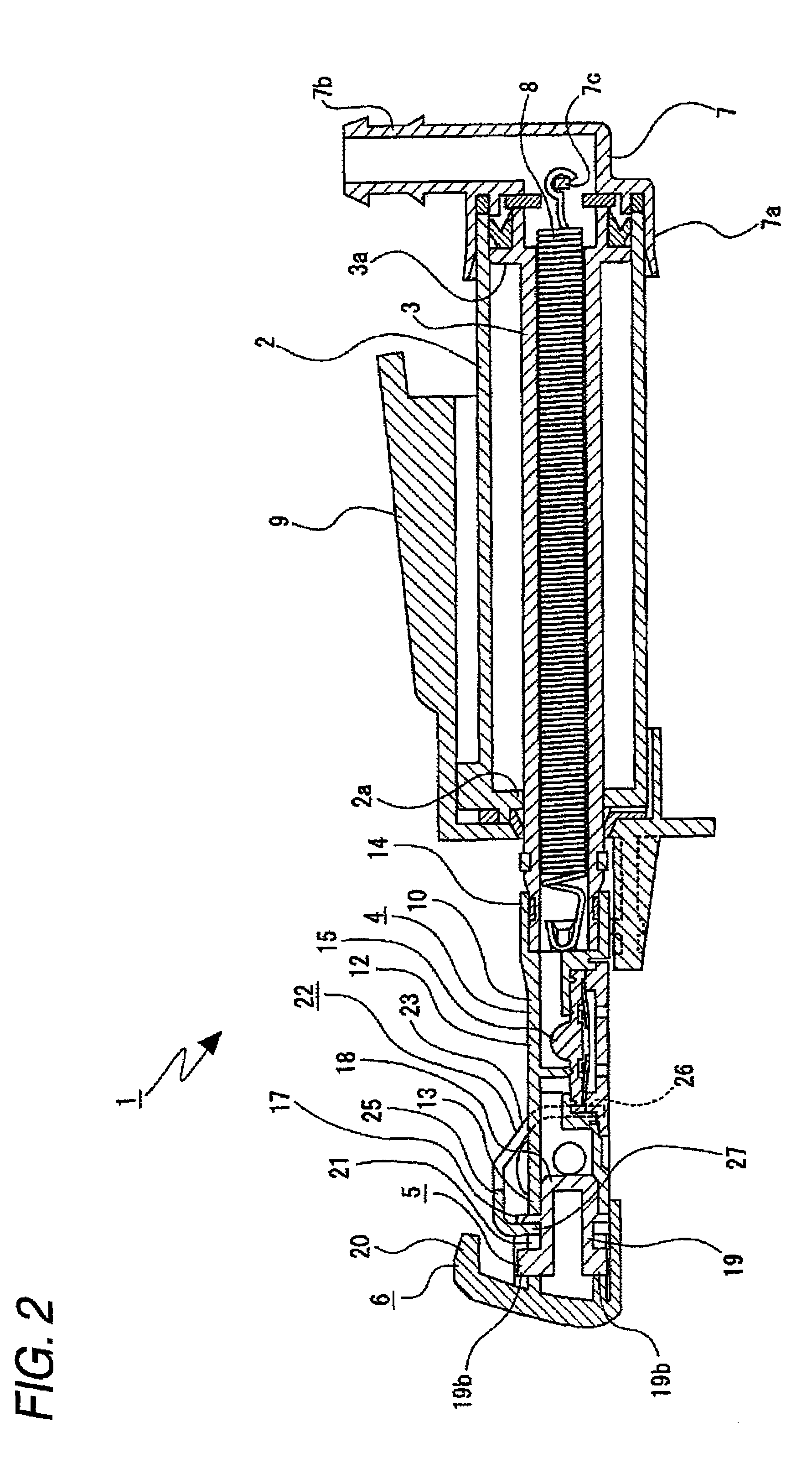
[0025]A cleaning apparatus 1, as shown in FIG. 1 and FIG. 2, includes a cylinder 2, a piston 3 slidably supported by the cylinder 2, a nozzle portion 4 connected to a front end of the piston 3, a holder 5 connected to a front end of the nozzle portion 4, and a nozzle cover 6 connected to the front end of the holder 5.

[0026]The cylinder 2 is formed in a substantially cylindrical shape, and has an inwardly overhung inner flange portion 2a at its front end (refer to FIG. 2).

[0027]A joint 7 is attached to a rear end of the cylinder 2 (refer to FIG. 1 and FIG. 2). The joint 7 has a cover portion 7a which blocks the rear end of the cylinder 2, and a connecting tube portion 7b continuous with the rear surface of the cover portion 7a. A spring hooking portion 7c is provided inside the cover portion 7a of the joint 7.

[0028]In a s...


PUM


Abstract

A nozzle portion having jet nozzles for jetting a cleaning liquid, a nozzle cover covering the nozzle portion from a front side, a piston connected to the nozzle portion, and moved integrally with the nozzle portion and the nozzle cover in a movement direction, and a cylinder movably supporting the piston are provided. A bracket which includes arms located in abutment with or in proximity with a rear surface of the nozzle cover and regulates an inclination of the nozzle cover with respect to the movement direction is provided.

Description

[0001]This application claims foreign priority from Japanese Patent Application No. 2007-257662 filed on Oct. 1, 2007, the entire contents of which are hereby incorporated by reference.BACKGROUND OF THE INVENTION[0002]1. Field of the Invention[0003]The present invention relates to a cleaning apparatus of a vehicle lamp. Specifically, the present invention relates to the cleaning apparatus in which a nozzle cover is prevented from unfastening from a nozzle portion.[0004]2. Background Art[0005]There is a cleaning apparatus which is movable to protrude from and retract into an opening formed in a vehicle body or a bumper, and cleans a front cover of a vehicle head lamp.[0006]Such a cleaning apparatus (for example, refer to JP-A-2006-335273) includes: a nozzle portion having jet nozzles for jetting a cleaning liquid; a nozzle cover for covering the nozzle portion from a front side; a piston connected to the nozzle portion; and a cylinder movably supporting the piston. An opening formed ...

Claims


Application Information

Patent Timeline
Patent Type & Authority Patents(United States)
IPC IPC(8): B08B3/00
CPCB60S1/528
Inventor NAKADA, KATSUMITAKADA, HIROMASA
Owner KOITO MFG CO LTD
Learn More