Multi-vane centrifugal fan

a centrifugal fan, multi-vane technology, applied in the direction of machines/engines, stators, liquid fuel engines, etc., can solve the problems of aerodynamic noise source, and achieve the effect of increasing the rotational state of the fan

Active Publication Date: 2007-07-17
DAIKIN IND LTD
View PDF19 Cites 33 Cited by
  • Summary
  • Abstract
  • Description
  • Claims
  • Application Information

AI Technical Summary

Benefits of technology

[0010]Aspects of the present invention solve such problems, with a shroudless multi-vane centrifugal fan as discussed above, wherein the bell mouth having a recessed part of a prescribed depth is provided around the circumference of the air suction port, and the air suction port side end part of each vane is sealably shaped corresponding to the cross sectional shape of the recessed part of the bell mouth. Thereby, a multi-vane centrifugal fan is provided that reliably solves the problems discussed above, and reduces running noise as much as possible.
[0022]In addition, because the annular member is disposed on the outer side of the vanes in the radial direction, and because the spaces interposed by adjacent vanes are completely open in the shaft core direction and in the direction of the side opposite the hub, the annular member and the vanes can be easily formed by integral molding.

Problems solved by technology

This is also a source of aerodynamic noise.

Method used


Image

  • Multi-vane centrifugal fan
  • Multi-vane centrifugal fan
  • Multi-vane centrifugal fan

Examples


first embodiment

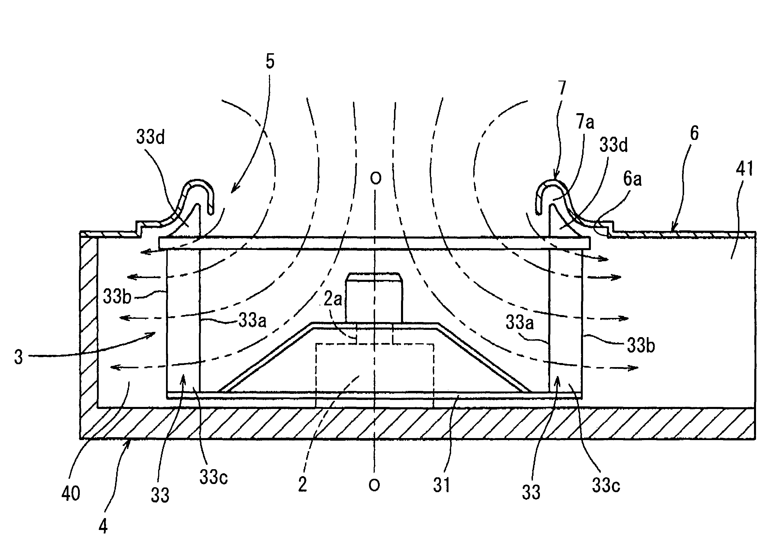
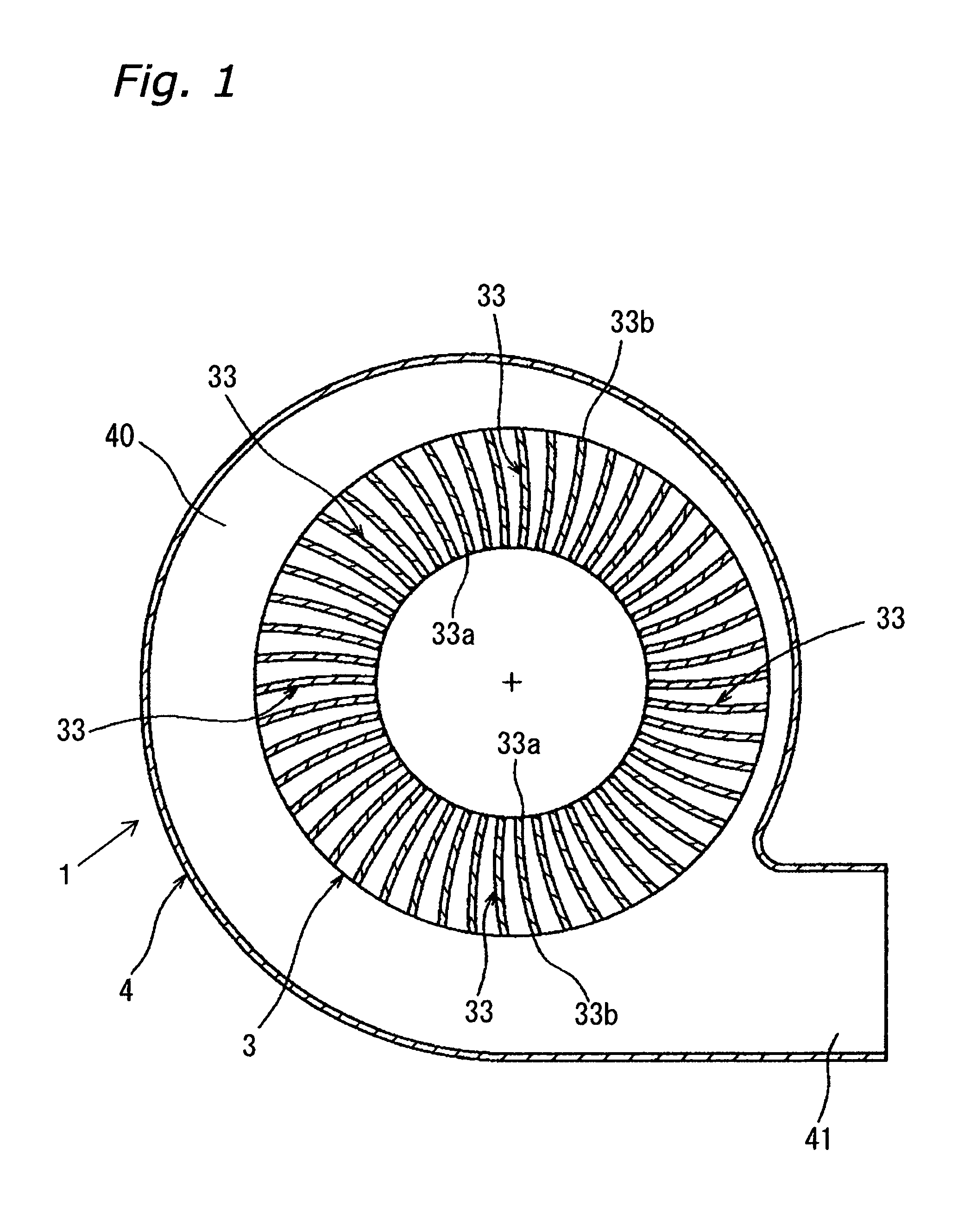
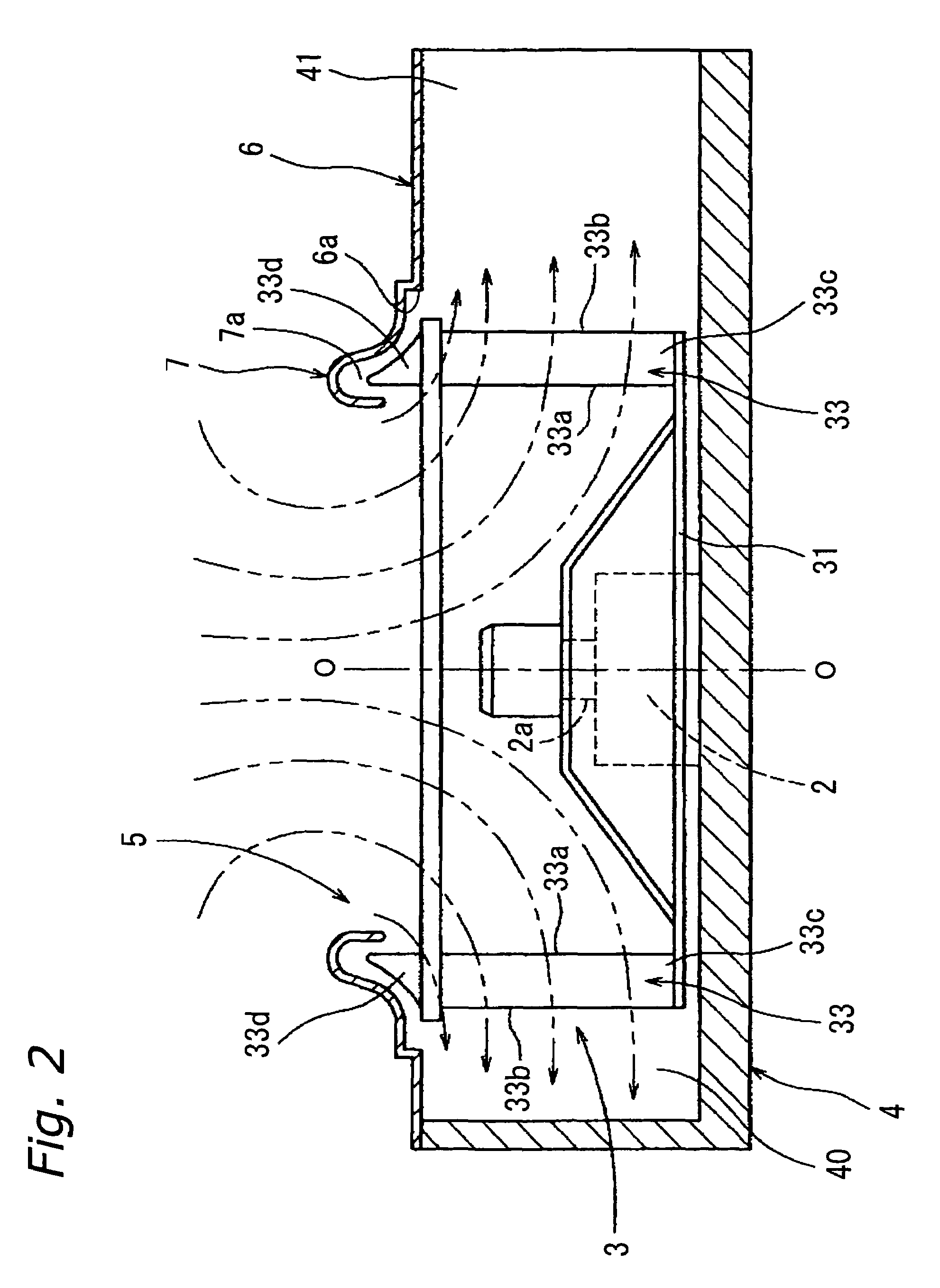
[0032]FIG. 1 through FIG. 3 depict the constitution of the multi-vane centrifugal fan according to the first embodiment of the invention of the present application. This multi-vane centrifugal fan 1 comprises an impeller drive motor 2, an impeller 3, and a fan housing 4, as depicted in FIG. 1 and FIG. 2. The impeller 3 is supported by a rotary shaft 2a of the impeller drive motor 2, and is rotatably driven by the impeller drive motor 2. The fan housing 4 rotatably houses the impeller 3 via the rotary shaft 2a of the impeller drive motor 2. This fan housing 4 comprises an air suction port forming plate 6, a bell mouth 7, and the like. The air suction port forming plate 6 forms an air suction port 5. The air suction port 5 is positioned concentric with a rotational axis O-O (shaft core) of the impeller 3, and has a size corresponding to the inner diameter of the impeller 3. The bell mouth 7 is positioned around the circumference of the air suction port 5.

[0033]The impeller 3 comprises...

second embodiment

[0048]FIG. 5 depicts the constitution of the vane portion of the multi-vane centrifugal fan according to the second embodiment of the invention of the present application.

[0049]Here, the shape of the notched part of the air suction port side end part 33d in the constitution of the abovementioned first embodiment is modified to a shape wherein the vane width from the air inlet side edge part 33a to each of the air outlet side edge parts 33b, 33b, . . . decreases linearly from W1 to W2, as depicted in FIG. 5.

[0050]With such a shape as well, the clearance between the air suction port side end parts 33d, 33d, . . . of the vanes 33, 33, . . . and the recessed part 7a of the bell mouth 7 can be reduced, sealing performance can be ensured, and reverse flow can be suppressed; thereby, with this case as well, leakage flow in the vicinity of the bell mouth 7 can be suppressed, and ventilation noise can be reduced.

third embodiment

[0051]FIG. 6 depicts the constitution of the vane portion of the multi-vane centrifugal fan according to the third embodiment of the invention of the present application.

[0052]Here, the shape of the notched part of the air suction port side end part 33d in the constitution of the abovementioned first embodiment is made to vary by decreasing in a curved shape (more specifically, an S-shaped curve) from the air inlet side edge part 33a to each of the air outlet side edge parts 33b, 33b, . . . , as depicted in FIG. 6.

[0053]The notched part of the air suction port side end part 33d can be modified to a variety of curved shapes from the air inlet side edge part 33a to each of the air outlet side edge parts 33b, 33b, . . . ; however, if substantially S-shaped as mentioned above, then the entirety of the air suction port side end part 33d can particularly be made to correspond to the cross sectional shape of the recessed part 7a of the bell mouth 7.

[0054]Thus, in this case, because the cle...


PUM


Abstract

A multi-vane centrifugal fan has a fan housing and an impeller. The impeller includes a plurality of vanes arranged with a prescribed spacing in the circumferential direction and fixed to a hub rotatably driven around a shaft core. The impeller further includes an annular member for reinforcement that is provided on a side of the vanes opposite the hub. The fan housing has a bell mouth with a recessed part that is provided around a circumference of an air suction port of the fan housing. The recessed part has air suction port side end parts positioned on the side of the vanes opposite the hub and rotatably inserted in the recessed part without having a shroud.

Description

CROSS-REFERENCE TO RELATED APPLICATIONS[0001]This U.S. National stage application claims priority under 35 U.S.C. §119(a) to Japanese Patent Application Nos. 2003-126122, filed in Japan on May 1, 2003, and 2004-125427, filed in Japan on Apr. 21, 2004, the entire contents of which are hereby incorporated by reference.FIELD OF THE INVENTION[0002]The invention of the present application relates to the structure of a multi-vane centrifugal fan.RELATED ART[0003]Among multi-vane centrifugal fans, there is one as depicted in FIG. 7 through FIG. 9, for example. This multi-vane centrifugal fan comprises an impeller 103 and a fan housing 104.[0004]The impeller 103 comprises a hub 131, numerous vanes 133, 133, . . . and an annular member 132. With the impeller 103, one end 133c of the numerous vanes 133, 133, . . . are fixed to the hub 131 capable of rotating about a shaft core, and are provided and arranged spaced apart by a predetermined spacing in the circumferential direction. In addition,...

Claims


Application Information

Patent Timeline
Patent Type & Authority Patents(United States)
IPC IPC(8): F01D11/02F04D29/16F04D29/28F04D29/42
CPCF04D29/162F04D29/283F04D29/4213
Inventor YAMASAKI, TAKAHIRO
Owner DAIKIN IND LTD
Why Eureka
Try Eureka