
Valve treatment catheter and methods

a valve and treatment catheter technology, applied in balloon catheters, medical science, surgery, etc., can solve the problems of stenotic valves not being able to fully open, requiring more work, and heart valve disease is a serious health problem, and achieve the effect of effective treatment of biological passages containing valves

Inactive Publication Date: 2007-07-17
BOSTON SCI SCIMED INC
View PDF789 Cites 43 Cited by
  • Summary
  • Abstract
  • Description
  • Claims
  • Application Information

AI Technical Summary

Benefits of technology

The invention provides a catheter with an inflatable balloon assembly for delivering therapeutic fluid to a treatment site in a biological passage containing a valve. The balloon assembly is designed to engage the biological passage and create a plurality of containment pockets where the therapeutic fluid can be delivered. The inflated balloon assembly defines a flow lumen through which the therapeutic fluid can flow, while a valve contained within the balloon assembly functions to allow the fluid to flow in a physiologic direction and block backflow. The invention provides improved devices and methods for effectively treating a biological passage containing a valve, offering flexibility in treatment duration and type of therapeutic agent delivered.

Problems solved by technology

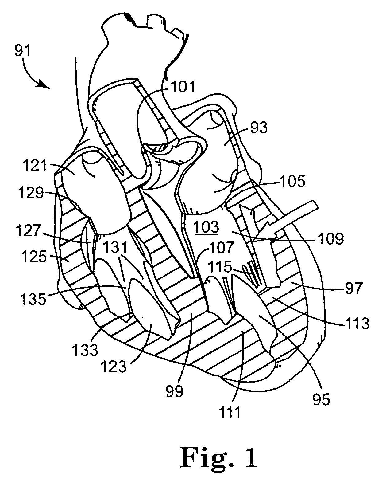
Heart valve disease is a serious health problem facing society today.
Stenotic valves cannot open fully, requiring more work to push the liquid through the valve.
As a result of stenosis or incompetence, the heart must work harder to provide the same level of blood circulation, and in many cases the heart becomes incapable of sustaining an active lifestyle.
Rheumatic fever stiffens valve tissue, causing stenosis.
Congenitally defective valves do not form properly as the heart develops, but often go unnoticed until adulthood.
Bacterial infection of the heart can cause inflammation of valves, tissue scarring, or permanent degradation.
Many of these damaged valves have to be replaced in order for the patient to live a normal life, since the strain on their heart would otherwise cause such symptoms as chest pain, fatigue, shortness of breath, and fluid retention.
While each of these options has benefits, there are drawbacks associated with each.
However, the mechanical leaflets do not close completely, which allows some backflow.
Since backflow is one of the properties of defective valves, the bileaflet valves are still not ideal valves.
As a result of the less-than-ideal flow properties of the valve, these valves can cause the heart to work harder to pump blood.
The resulting stress on the heart can damage heart muscle and blood cells in the vicinity of the valve.
The most common cause of bioprosthesis failure is stiffening of the tissue due to the build up of calcium.
Calcification can cause a restriction of blood flow through the valve (stenosis) or cause tears in the valve leaflets, thereby requiring a subsequent valve replacement.
Further, bioprosthetics generally do not integrate well with the host organism and eventually die.
However, this alternative is not commonly seen, since most available human hearts are directed to whole-heart transplants, rather than valve-only transplants.
In the case of systemic treatment, high concentrations of the therapeutic agent cannot be used in many cases, because of risk of undesirable side effects.
Thus, current treatment options for heart valve disease have several drawbacks.

Method used


Image

  • Valve treatment catheter and methods
  • Valve treatment catheter and methods
  • Valve treatment catheter and methods

Examples


Embodiment Construction

[0039]The embodiments of the present invention described below are not intended to be exhaustive or to limit the invention to the precise forms disclosed in the following detailed description. Rather, the embodiments are chosen and described so that others skilled in the art can appreciate and understand the principles and practices of the present invention.

[0040]The present invention is directed to methods and apparatuses for effectively treating a biological passage, and in particular for delivering therapeutic agents to a valve within a biological passage. Such methods and apparatuses in accordance with the present invention can advantageously be used to provide flexibility in treatment duration and type of therapeutic agent delivered to the valve. In particular, the present invention has been developed for delivering one or more therapeutic agents to a valve while maintaining blood flow through the biological passage in a physiologic manner. Such devices (for example, catheters)...


PUM


Abstract

The invention provides a catheter for insertion into a biological passage which contains a first flowing fluid, the catheter including a tubular member having a proximal end and a distal end; a fluid delivery lumen contained within the tubular member; an inflatable balloon assembly disposed at the distal end of the tubular member, the balloon assembly including an inflatable balloon member having an uninflated state and an inflated state, the balloon assembly including apertures in communication with the fluid delivery lumen; an inflation lumen in communication with the balloon member; and a valve contained within the inflatable balloon assembly. The inflatable balloon is assembly configured such that when the balloon member is in the inflated state: (i) sections of the balloon member contact the biological passage defining at least one containment pocket; (ii) the apertures are disposed in the containment pocket, (iii) a flow lumen is defined through the balloon member to allow the first fluid to flow through the balloon member; and (iv) the valve functions to allow the first flowing fluid to flow through the flow lumen in a physiologic direction, while blocking backflow of the first fluid through the flow lumen.

Description

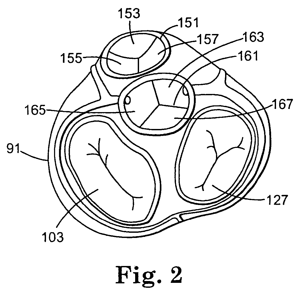
[0001]This application is a continuation of U.S. application Ser. No. 10 / 334,399, filed Dec. 30, 2002, now U.S. Pat. No. 6,945,957, the entire specification of which is incorporated herein by reference.FIELD OF THE INVENTION[0002]The invention relates to treatment of a biological passage containing a valve. More particularly, the invention provides a catheter having a blood flow lumen containing a valve that mimics the native valve to be treated. The valve of the inventive device permits blood flow in a physiologic direction while blocking backflow.BACKGROUND OF THE INVENTION[0003]Heart valve disease is a serious health problem facing society today. There are approximately 225,000 surgeries annually to repair damaged heart valves. Of these surgeries, at least 60,000 Americans receive replacements for valves damaged by congenital or rheumatic heart disease.[0004]Cardiac valves have three functional properties: (1) preventing regurgitation of blood flow (also referred to as retrograde...

Claims


Application Information

Patent Timeline
Patent Type & Authority Patents(United States)
IPC IPC(8): A61M29/00A61F2/958A61M25/00
CPCA61M25/007A61M25/0075A61M25/1002A61M25/1011A61F2/2403A61F2/2412A61F2/2424A61F2/2433A61F2/2496A61F2250/0059A61M25/0029A61M2025/0034A61M2025/0076A61M2025/1047A61M2025/105A61M2025/1072
Inventor FREYMAN, TOBY
Owner BOSTON SCI SCIMED INC
Learn More