
Vehicle electronic key system

a technology of electronic keys and vehicles, applied in the field of electronic keys, can solve the problems of low possibility of electronic keys being lost after use, low probability of losing electronic keys, and the loss of keys, and achieve the effect of extremely low probability of losing the portable transceiver

Inactive Publication Date: 2007-07-17
HONDA MOTOR CO LTD
View PDF36 Cites 11 Cited by
  • Summary
  • Abstract
  • Description
  • Claims
  • Application Information

AI Technical Summary

Benefits of technology

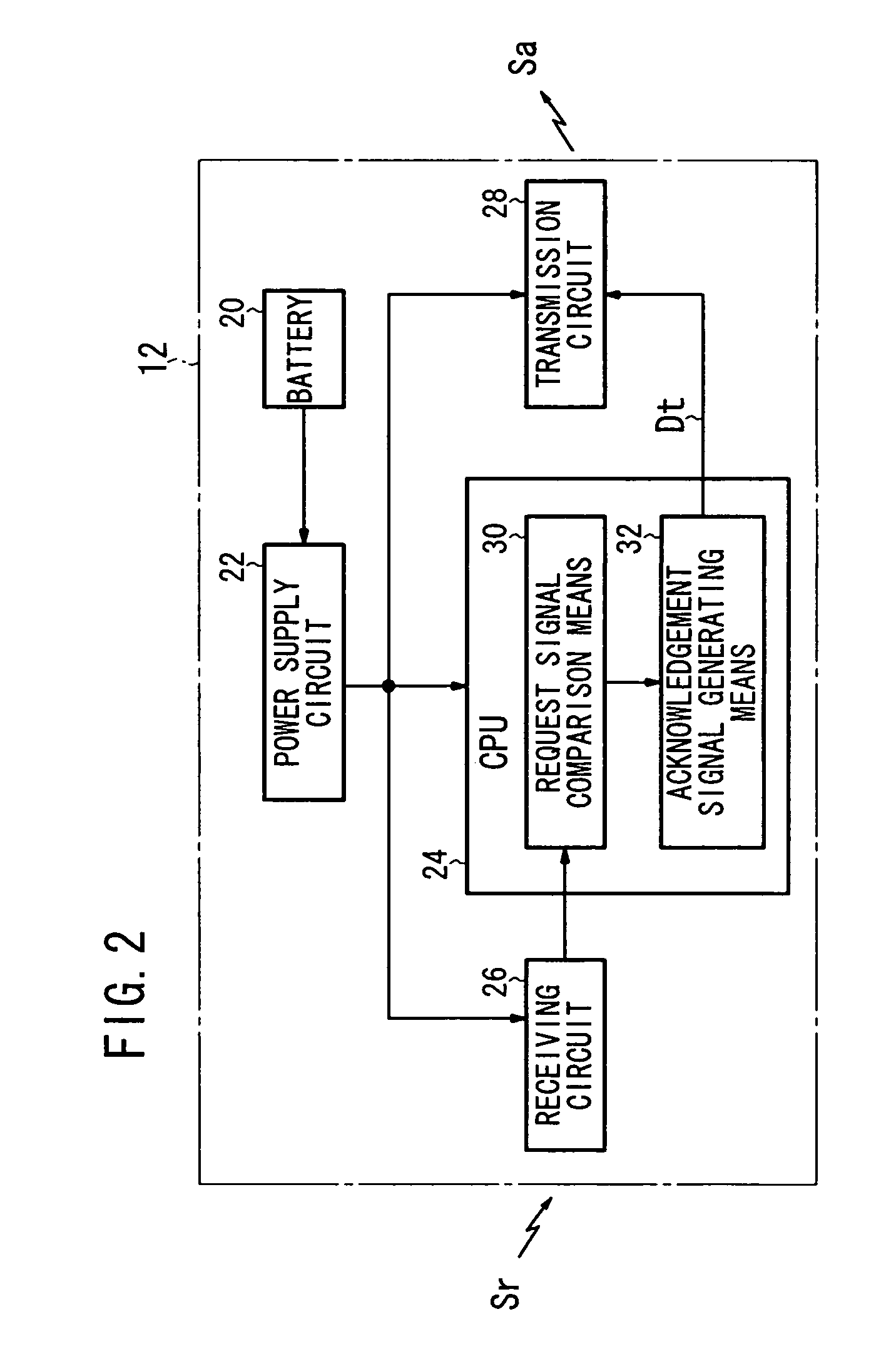
The present invention is an electronic key system for vehicles that includes a controller and a portable transceiver for transmitting ID data based on a request signal from the controller. The system has first means for outputting a request signal to the portable transceiver when the user activates the start switch for the vehicle, second means for detecting an acknowledgement signal from the portable transceiver, and third means for outputting a warning if the acknowledgement signal is not detected. The system also includes a controller mounted on the vehicle and a portable transceiver for transmitting an acknowledgement signal based on the request signal from the controller. The system can make the user aware of the fact that the portable transceiver has been dropped, reducing the likelihood of losing it. The output period for the request signal is preferably 10 to 100 seconds to improve battery consumption.

Problems solved by technology

Since the electronic key is carried by the user, there is a danger of the key being dropped inside the vehicle when the key is not in use.
In the case of a four-wheeled vehicle, however, there is only a very low possibility of the electronic key being lost after use, even if it is dropped inside the vehicle.
However, if the motorcycle moves without noticing that the key has been dropped, the key may become lost and it will not be possible to restart the engine.
As a result, if the electronic key is dropped during travel, for instance, there is a danger that it will not be detected.
Naturally, even with a four-wheeled vehicle, if the electronic key is dropped close to the door, the probability of the electronic key becoming lost is high, and in this case also, it will not be possible to restart the engine.

Method used


Image

  • Vehicle electronic key system
  • Vehicle electronic key system
  • Vehicle electronic key system

Examples


Embodiment Construction

[0036]Embodiments of the electronic key system for a vehicle of the present invention applied to a system for a motorcycle (hereinafter, simply referred to as electronic key system embodiments) will now be described with reference to FIGS. 1 through 8F.

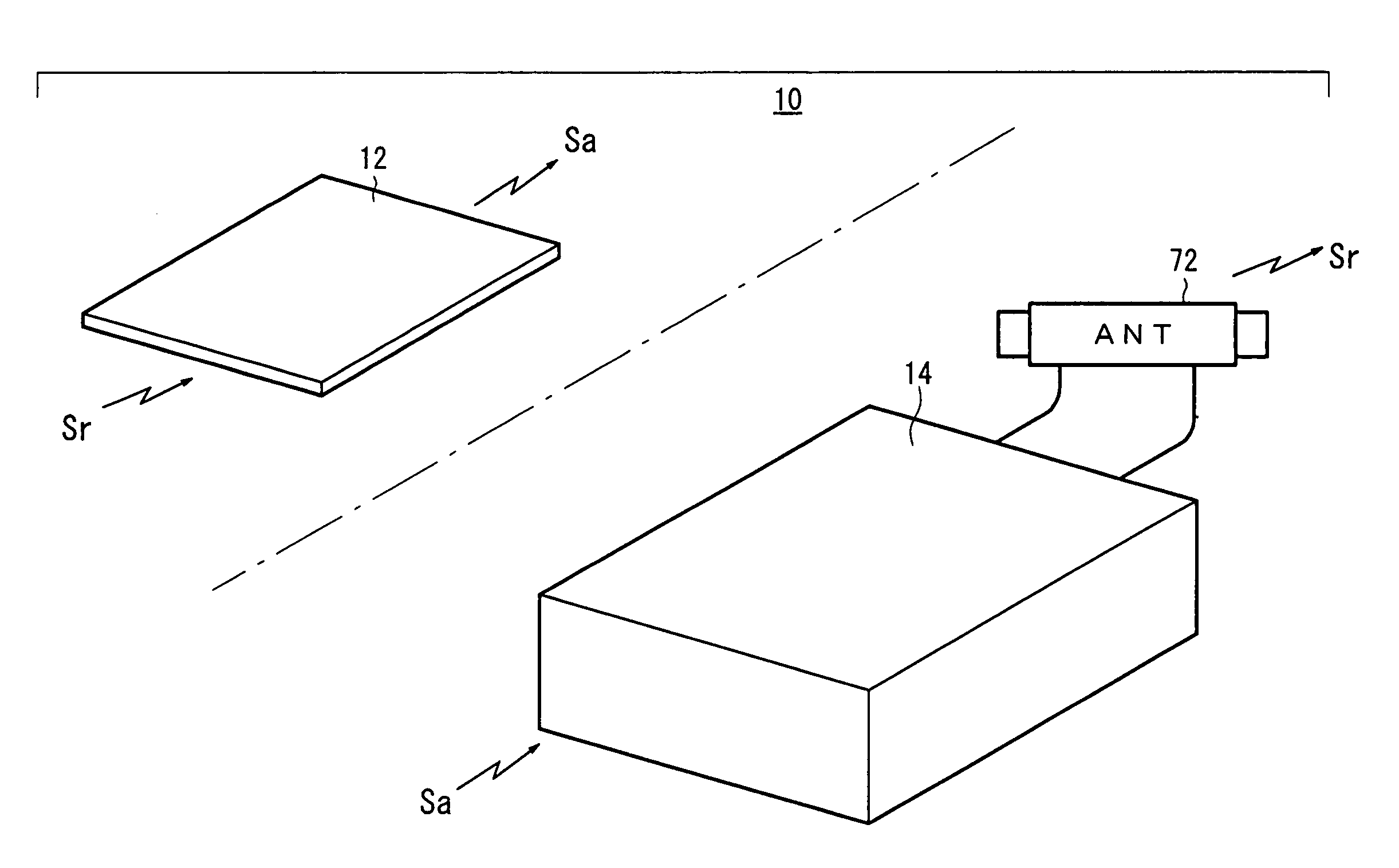
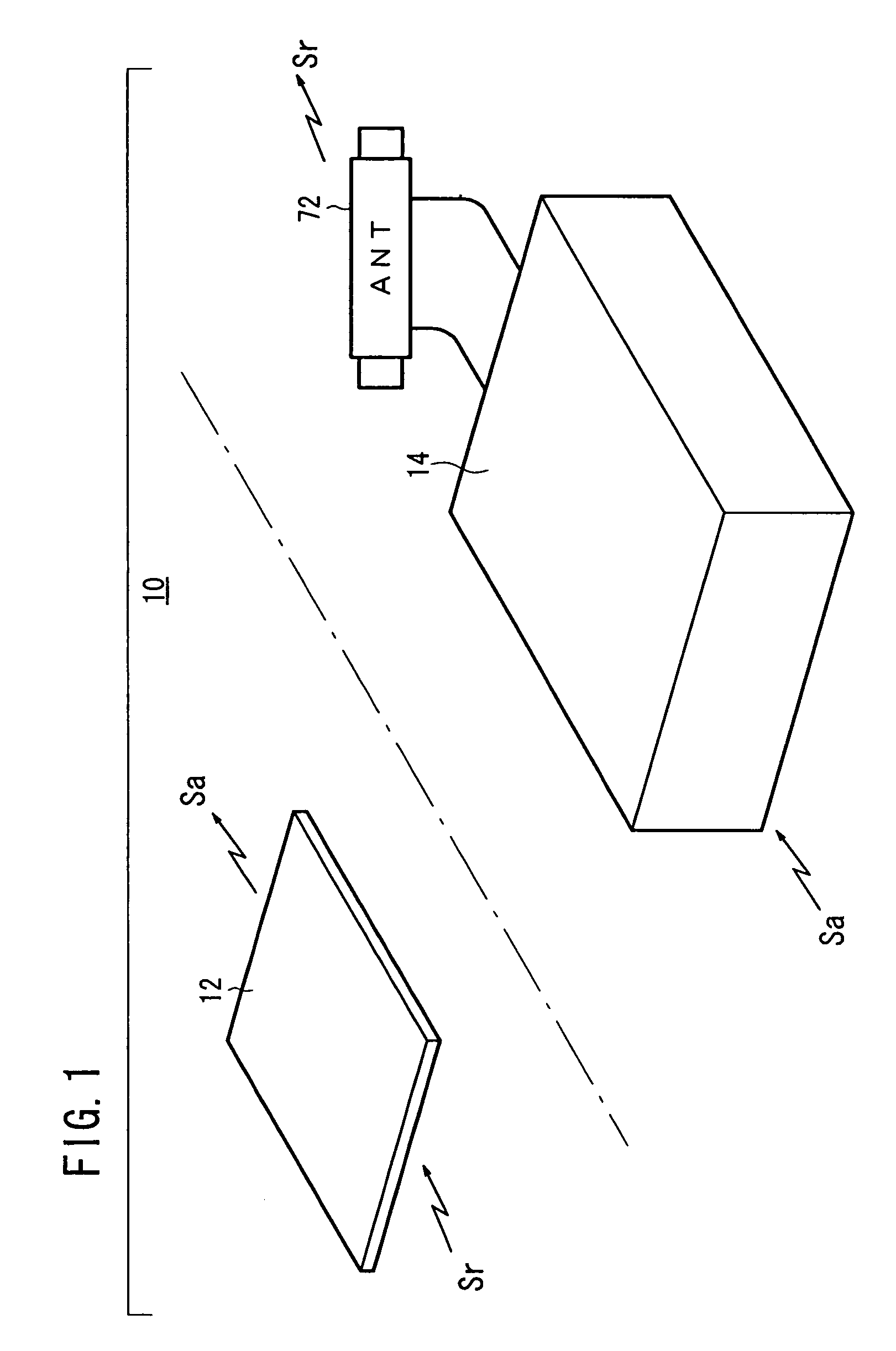
[0037]As shown in FIG. 1, an electronic key system 10 of this embodiment comprises a portable transceiver 12 carried by a user, and a controller 14 mounted on the vehicle. The portable transceiver 12 can be either a key type having an IC chip built-in or a card type having an IC chip built in, however, in the case where a keyless system is adopted, the card type is mainly used. In this embodiment, a description will be given assuming that the portable transceiver 12 comprises a card type. Also, since the portable transceiver 12 is generally called an electronic key, in the following description, the portable transceiver will also be referred to as an electronic key.

[0038]The electronic key 12 is a card type, as described above, and as...


PUM


Abstract

A vehicle electronic key system includes a control device mounted on a vehicle and an electronic key for transmitting a response signal in response to reception of a request signal from the control device. The control device includes means for outputting a request signal to the electronic key in response to the ON operation of a main switch of the vehicle (request signal generation means, a transmission circuit, and a transmission antenna), means for detecting a response signal from the electronic key (a reception circuit and response signal matching means), and means for performing an alarm output (monitoring means, a third drive circuit, and an alarm lamp) when no response signal is detected in spite of the output of the request signal.

Description

TECHNICAL FIELD[0001]The present invention relates to an electronic key system for carrying out wireless communication between a transceiver (electronic key) carried by a user and a controller mounted on the vehicle, and, when an ID is compared and there is a request from the normal user, starting the engine etc., the invention being suitable for use as, for example, an electronic key system for a vehicle such as a motorcycle.BACKGROUND ART[0002]Japanese Laid-Open Patent Publication No. 2001-349110 and Japanese Laid-Open Patent Publication No. 2001-349117 exist as known examples of electronic key systems for a vehicle. The electronic key systems for a vehicle disclosed in these patent documents have activation means (switches) arranged in a door handle and trunk lid of the vehicle. If a user operates (activates) these activation means, communication with the electronic key commences, comparison is carried out between an ID transmitted from the electronic key and an ID registered in ...

Claims


Application Information

Patent Timeline
Patent Type & Authority Patents(United States)
IPC IPC(8): G05B19/00B60R25/10H04B1/00H04B17/00H04Q7/00E05B49/00B60R25/01B60R25/04B60R25/24B62H5/00G07C9/00
CPCB60R25/04B60R25/102B60R25/2009B60R25/246B60R25/248G07C9/00309G07C2209/63G07C2009/00793G07C2209/08G07C2209/62B60R2325/306B60R25/104
Inventor KONNO, TAKESHI
Owner HONDA MOTOR CO LTD
Learn More