Mobile radio antenna radome with integral reflector

a mobile radio antenna and reflector technology, applied in the direction of antennas, antenna details, antenna couplings, etc., can solve the problems of becoming detached from the radome material, achieve the effect of reducing the total number of components, improving the back-to-front ratio, and simplifying the overall assembly complexity

Active Publication Date: 2007-07-17
TELEFON AB LM ERICSSON (PUBL)
View PDF35 Cites 15 Cited by
  • Summary
  • Abstract
  • Description
  • Claims
  • Application Information

AI Technical Summary

Benefits of technology

[0019]A radome such as this forming an incorporated reflector can be used to improve the back-to-front ratio.
[0020]This is because the use of a radome such as this for a mobile radio antenna with a separate reflector on which the antenna elements and antenna element structures are formed effectively results in a double reflector.
[0021]The exemplary illustrative radome thus has a large number of advantages. In comparison to conventional solutions, the exemplary illustrative solution with a reflector incorporated in the radome material leads to the radome being lighter overall, to the incorporated reflector being better protected, and the entire ra...

Problems solved by technology

In particular, when additional reflector devices such as these were adhesively bonded to the radome material in the prior art, ther...

Method used


Image

  • Mobile radio antenna radome with integral reflector
  • Mobile radio antenna radome with integral reflector
  • Mobile radio antenna radome with integral reflector

Examples


Embodiment Construction

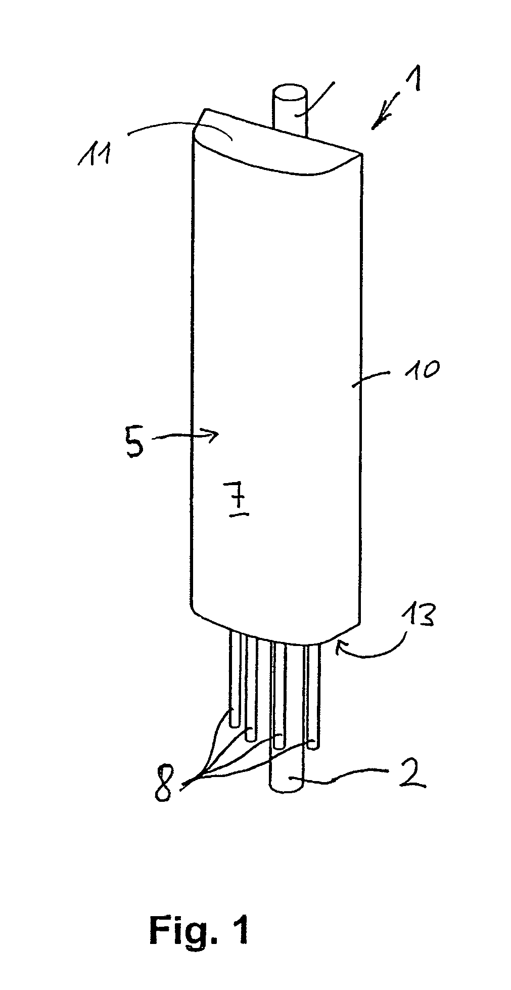
[0035]FIG. 1 shows a schematic illustration of a mobile radio antenna 1 which, for example, is part of a base station. The mobile radio antenna 1 is held and adjusted via a mast 2. In the interior, the mobile radio antenna 1 has a reflector 3, which cannot be seen in FIG. 1 but in front of which a large number of antenna elements, for example dipole antenna elements, patch antenna elements etc. are generally arranged, offset with respect to one another in the vertical direction.

[0036]The antenna elements may be any desired suitable antenna elements or antenna element groups as are known in principle, for example, from the prior publications DE 197 22 742 A1, DE 196 27 015 A1, U.S. Pat. No. 5,710,569, WO 00 / 39894 or DE 101 50 150 A1.

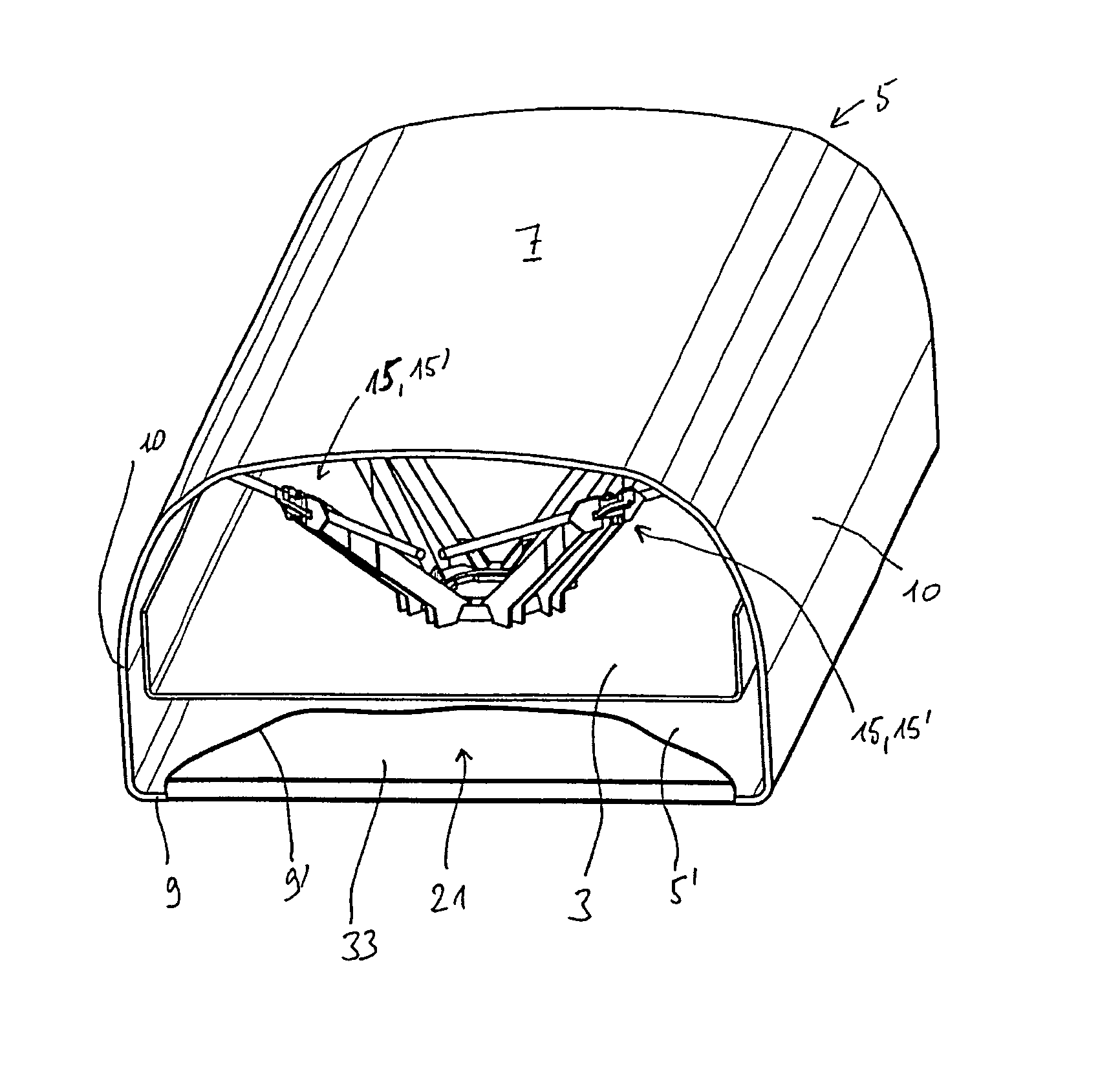
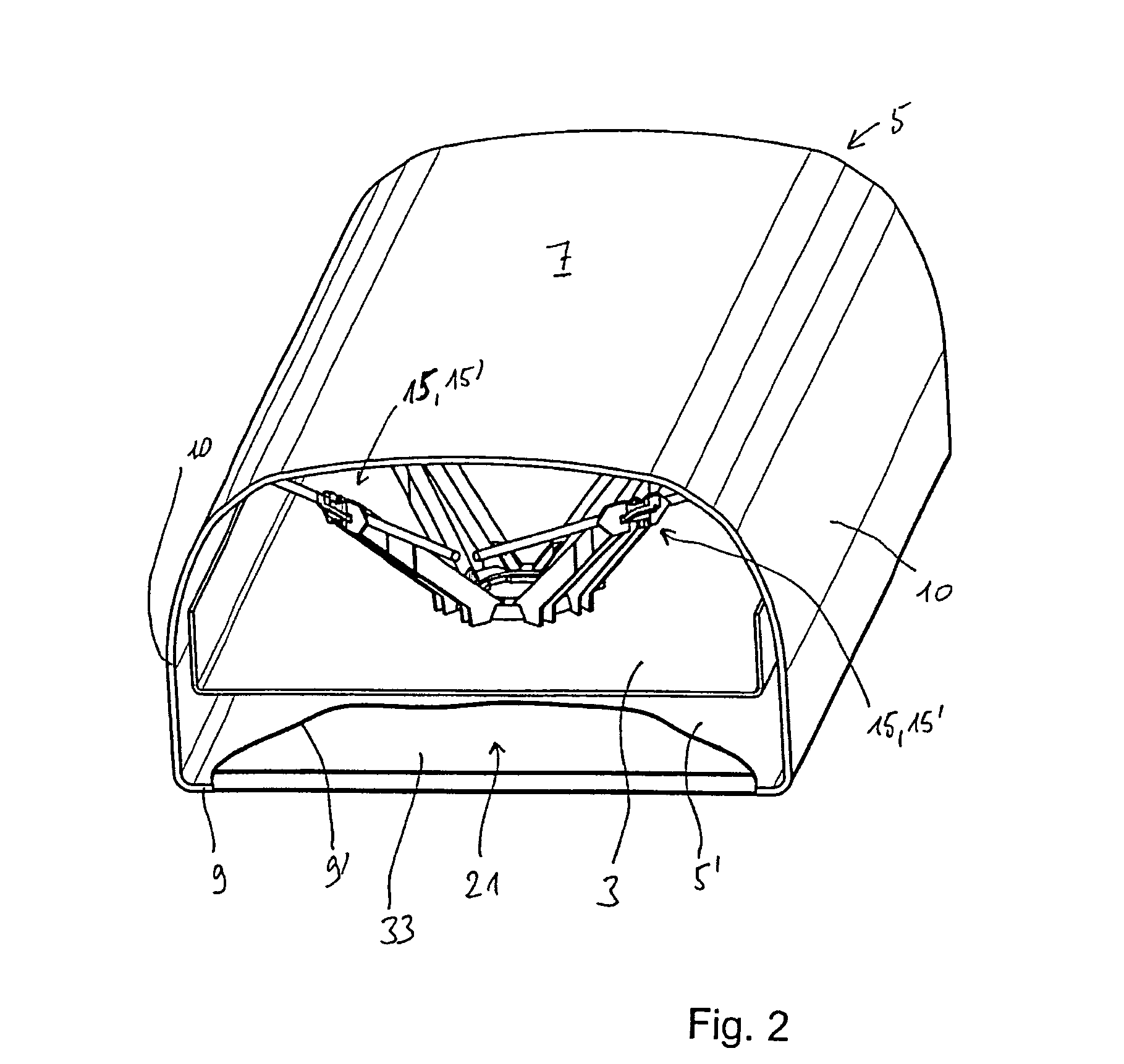
[0037]The antenna elements or antenna element groups are accommodated in a protected manner underneath a radome 5, with the radome 5 generally being produced as an integral body which is closed in the circumferential direction and has a front face 7 which...


PUM


Abstract

An improved radome comprises at least one conductive flat structure integrally incorporated in the material of the radome, which acts as a reflector for a mobile radio antenna at least partially enclosed within the radome.

Description

FIELD[0001]The technology herein relates to a radome for mobile radio antennas, and to an associated mobile radio antenna.BACKGROUND AND SUMMARY[0002]Mobile radio antennas for base stations normally have a vertically running conductive reflector which may possibly also be provided with webs, edge boundaries etc. which run in the longitudinal or vertical direction and are offset outwards from the center, and which extend such that they run at right angles to the reflector plane or at an angle to it. Two or more antenna elements or antenna element groups which are offset in the vertical direction are generally arranged in front of the reflector and, for example, can transmit and / or receive in one polarization or else in two mutually perpendicular polarizations.[0003]The dual-polarized antenna elements are frequently aligned at angles of +45° and −45° to the vertical (and to the horizontal), so that they are also referred to as X-polarization antenna elements.[0004]The antenna elements...

Claims


Application Information

Patent Timeline
IPC IPC(8): H01Q1/42
CPCH01Q1/246H01Q1/425H01Q1/52H01Q15/142H01Q19/021H01Q19/104
Inventor GOTTL, MAXIMILIANOBERMAIER, JOHANN
Owner TELEFON AB LM ERICSSON (PUBL)
Why Eureka
Try Eureka