Microwave antenna made of metamaterials

A technology of microwave antennas and metamaterials, which is applied in the directions of antennas, electrical components, and radiation unit covers, can solve the problems of increasing the rear lobe and reducing the front-to-back ratio of microwave antennas, so as to reduce electromagnetic waves, increase the front-to-back ratio, and ensure high efficiency. Effect

Inactive Publication Date: 2012-10-24
KUANG CHI INST OF ADVANCED TECH +1
View PDF4 Cites 6 Cited by
  • Summary
  • Abstract
  • Description
  • Claims
  • Application Information

AI Technical Summary

Problems solved by technology

However, while the transmitter is reflecting electromagnetic waves, the radiation generated by the edge current at the edge R' of the reflector causes the microwave antenna to have a larger backward radiation, that is, the rear lobe is larger, which reduces the front-to-back ratio of the microwave antenna; at the same time, the feed Diffraction electromagnetic waves are also formed at the edge R' of the reflector to form backward radiation, which further increases the rear lobe and reduces the front-to-back ratio of the microwave antenna.

Method used


Image

  • Microwave antenna made of metamaterials
  • Microwave antenna made of metamaterials
  • Microwave antenna made of metamaterials

Examples


Embodiment Construction

[0026] The present invention will be further described below in conjunction with relevant drawings and specific embodiments:

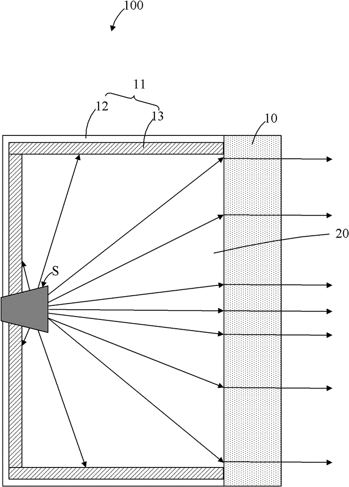
[0027] figure 2 It is a schematic cross-sectional structure diagram of a microwave antenna 100 in an implementation of the present invention, and the microwave antenna 10 includes a feed source S, a metamaterial unit 10 and an antenna cavity 11 . An opening 20 is provided on one side of the antenna cavity 11 , and the metamaterial unit 10 is disposed at the opening 20 to seal the feed source S in the microwave antenna 100 . The antenna cavity 11 includes a shell 12 and a wave absorbing unit 13 , the wave absorbing unit 13 is used to absorb electromagnetic waves and is coated on the inner surface of the shell 12 . In this embodiment, the housing 12 is made of metal material.

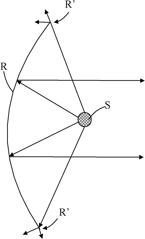
[0028] The feed S produces an electromagnetic radiation area in its surrounding space. In the feed pattern, it usually contains two or more lobes. The lobe with the highest rad...


PUM


Abstract

The invention relates to a microwave antenna made of metamaterials. The microwave antenna comprises a feed source, a metamaterial unit and a wave absorbing unit, wherein the metamaterial unit is used for refracting and gathering partial electromagnetic waves generated by the feed source, and the wave absorbing unit is used for absorbing the rest partial electromagnetic waves generated by the feed source. Therefore, the backwards radiated electromagnetic waves of the feed source are reduced, the front-to-rear ratio of the microwave antenna is obviously improved, and high efficiency of the microwave antenna is ensured.

Description

technical field [0001] The invention relates to a microwave antenna, in particular to a microwave antenna made of metamaterials. Background technique [0002] Transmitting or receiving antennas working in the meter wave, decimeter wave, centimeter wave, millimeter wave and other bands are collectively referred to as microwave antennas. At present, reflective microwave antennas are basically composed of reflectors and feed sources (FH, Feed Horn), and can be roughly divided into parabolic antennas, horn parabolic antennas, and horn antennas according to the shape of the reflector. [0003] as attached figure 1 As shown, it is a schematic diagram of the parabolic antenna cross-section, and its composition includes two basic elements: a parabolic reflector R and a feed source S placed at the focus of the parabola. It can be seen from the common sense of those skilled in the art that the feed source S produces a "flat donut" electromagnetic radiation area within a certain spat...

Claims


Application Information

Patent Timeline
Patent Type & Authority Applications(China)
IPC IPC(8): H01Q19/06H01Q15/00H01Q15/02H01Q17/00H01Q1/42
Inventor 刘若鹏徐冠雄张洋洋
Owner KUANG CHI INST OF ADVANCED TECH
Why Eureka
Try Eureka