Bifilar helical antenna

a helical antenna and helical technology, applied in the direction of antenna details, non-resonant long antennas, antennas, etc., can solve the problems of increasing the difficulty of fabrication process, increasing the breakdown rate, and the operation mechanism of the feed network mentioned in literature looks somewhat more complicated, so as to improve the front-to-back ratio of field pattern, shorten the antenna length, and improve the effect of field pattern

Inactive Publication Date: 2006-09-26
NAT TAIWAN UNIV
View PDF7 Cites 6 Cited by
  • Summary
  • Abstract
  • Description
  • Claims
  • Application Information

AI Technical Summary

Benefits of technology

[0013]Yet another objective of the present invention is to provide a bifilar helical antenna operable in either a normal mode or an axial mode, both of which possess circular polarization. When the circumference of a helical line is shorter than a wavelength, the helix antenna is operated in the normal mode, where the main beam points laterally. When the circumference of a helical line is equal in length to a wavelength, the helix antenna is operated in the axial mode, in which the traveling-wave characteristics allow the field pattern, input impedance, and polarization to exhibit a broadband behavior.
[0015]Yet another objective of the present invention is to provide a bifilar helical antenna, to a terminal of which a resistive load is arranged to hence shorten the length of antenna.
[0016]Yet another objective of the present invention is to provide a bifilar helical antenna, in which an impedance bandwidth of feed network is at least equivalent to the designs mentioned in documents while with an easier operation and a higher front-to-back ratio of field pattern.

Problems solved by technology

Another dual-band helical antenna of U.S. Pat. No. 6,184,844 adopts multiple feed networks that results in a complicated manufacture process and an increased breakdown rate.
However, the operation mechanism of feed network mentioned in literature looks somewhat more complicated to increase the difficulties of fabrication process.
However, its operation mechanism is rather complicated and hence its fabrication process is more difficult, and that is the reason why the present invention is presented.

Method used


Image

  • Bifilar helical antenna
  • Bifilar helical antenna
  • Bifilar helical antenna

Examples


Embodiment Construction

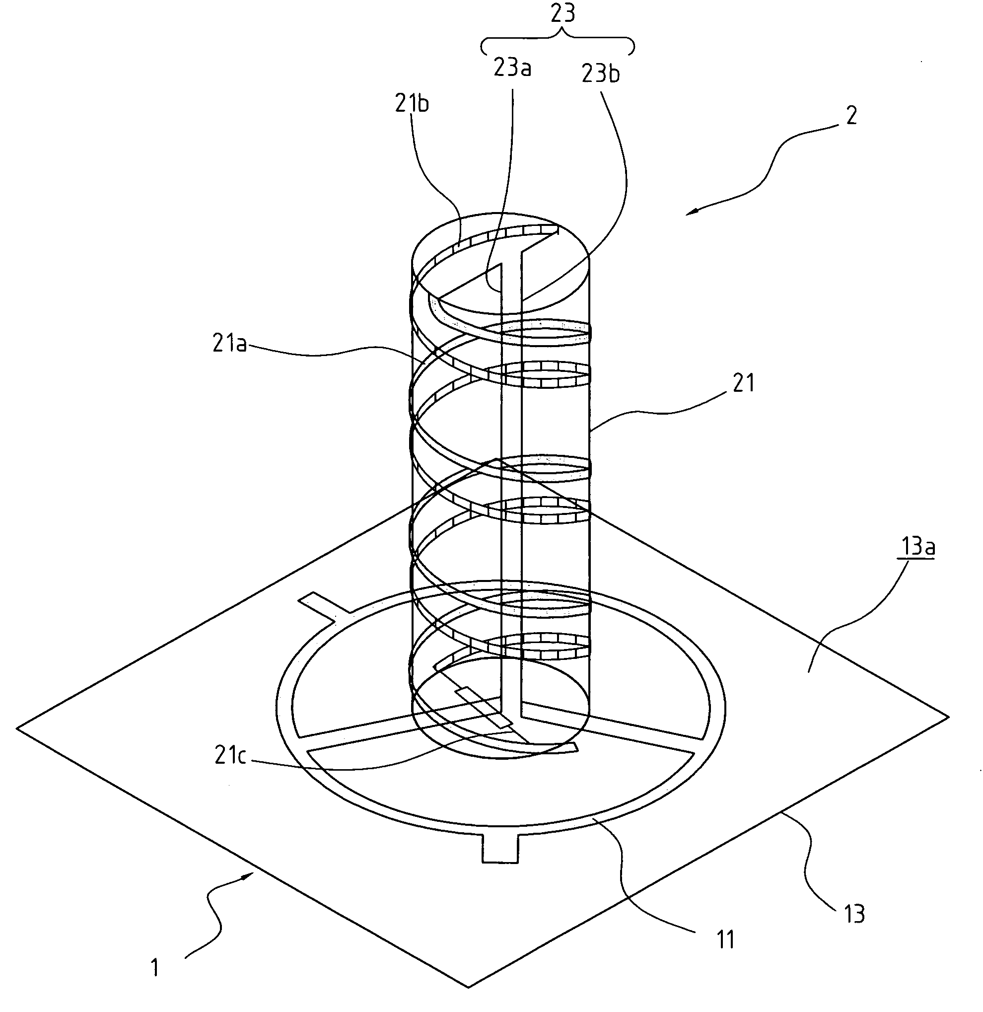
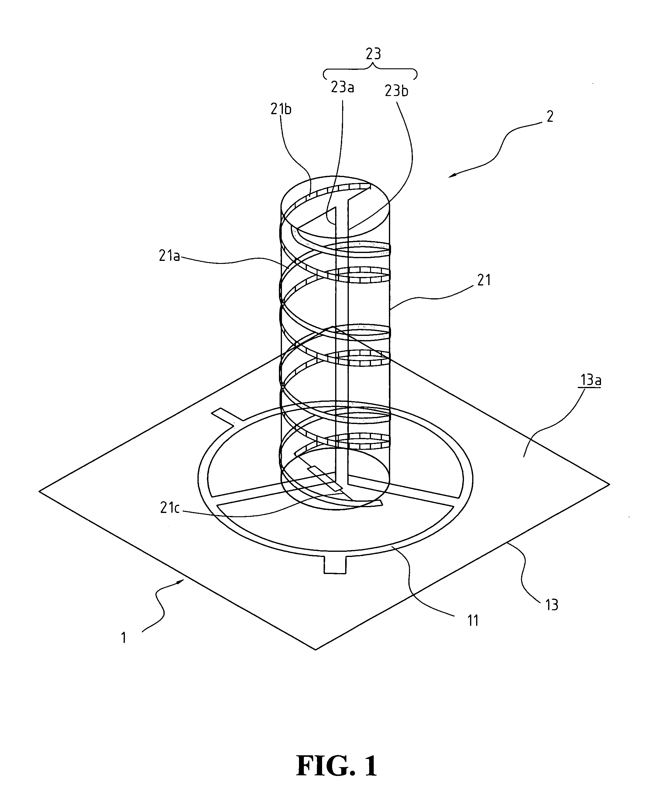
[0034]FIG. 1 is a perspective view showing a preferred embodiment of a bifilar helical antenna of the present invention; FIG. 2 is a partially top view of the bifilar helical antenna shown in FIG. 1; and FIG. 3 is a partially perspective view of the bifilar helical antenna shown in FIG. 1.

[0035]As shown in FIGS. 1–3, a bifilar helical antenna of the present invention is comprised of an output / input unit 1 and an antenna unit 2.

[0036]In the antenna architecture, the output / input unit 1 is built by laying a hybrid 11 on a substrate 13, in which the substrate 13 could be an FR4 circuit board, alumina board, ceramic board, etc., having a surface 13a coated with a metallic conductive layer; the hybrid 11 is a microstrip-line pattern formed by the metallic conductive layer on the surface 13a of the substrate 13, and consists of a ring part 11a and a plurality of transmission ports. Referring further to FIG. 2, the hybrid 11 is a broadband hybrid matched with the broadband characteristics ...


PUM


Abstract

A bifilar helical antenna includes an output / input unit formed by disposing a hybrid on a substrate, wherein the surface of the substrate is coated with a metallic conductive layer; the hybrid is a microstrip-line pattern formed by the conductive layer, and it further comprises a ring part and a plurality of transmission ports; and an antenna unit including a shell and an impedance transformer, wherein the shell is a cylindrical hollow tube disposed on the substrate of the output / input unit, on which a first helical line and a parallel second helical line are wound and both the bottom ends of the helical lines are electrically connected together through a resistor; the impedance transformer is composed of a first transmission line and a parallel second transmission line, where both the top ends of the first and the second transmission line are electrically connected to the top end of the first and the second helical line, and both the bottom ends of the first and the second transmission line are electrically connected to different transmission ports of the hybrid, respectively.

Description

BACKGROUND OF THE INVENTION[0001]1. Field of the Invention[0002]The present invention relates to the field of a bifilar helical antenna.[0003]2. The Prior Arts[0004]For wireless telecommunication, a bifilar helical antenna may generate a back-fire radiation suppose it is configured having a helix radius of 0.1 wavelength and a pitch angle of 10 degrees approximately, according to Nakano and Pattern. Such a back-fire beam of the bifilar helical antenna will be further split under the conditions of a helix radius of 0.1 wavelength and a pitch angle of 40 degrees according to Pattern's experiments, while the back-fire beam is circularly polarized under the conditions of a small radius and a pitch angle of 68 degrees approximately according to Nakano, in which the main beam will be moved laterally as the frequency goes higher.[0005]Since a bifilar helical antenna resembles a single-arm helix antenna in structure, therefore, the phase difference between one arm and the next is almost con...

Claims


Application Information

Patent Timeline
Patent Type & Authority Patents(United States)
IPC IPC(8): H01Q1/36
CPCH01Q11/08H01Q1/362
Inventor LAN, CHENG-WEIKIANG, JEAN-FUGAU, JING-JE
Owner NAT TAIWAN UNIV
Why Eureka
Try Eureka