End-fire planar circularly polarized antenna

A circularly polarized antenna, plane technology, applied in antennas, resonant antennas, electrical short antennas, etc., can solve the problems of low gain and narrow bandwidth, and achieve the effect of high gain, wide bandwidth and easy processing

Active Publication Date: 2017-11-24
BEIJING JIAOTONG UNIV
View PDF3 Cites 4 Cited by
  • Summary
  • Abstract
  • Description
  • Claims
  • Application Information

AI Technical Summary

Problems solved by technology

[0004] The problem with these existing designs is narrow bandwidth, including impedance bandwidth and axial ratio bandwidth, and low gain

Method used


Image

  • End-fire planar circularly polarized antenna
  • End-fire planar circularly polarized antenna
  • End-fire planar circularly polarized antenna

Examples


Embodiment 1

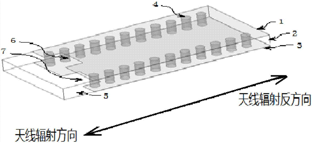
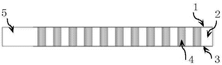
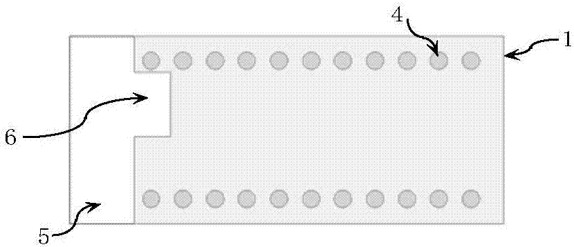
[0046] Such as figure 1 As shown, it is a three-dimensional structure diagram of the antenna described in Embodiment 1 of the present invention. The dielectric layer 2 can be made of Rogers5880, the thickness of the dielectric layer can be 1.575mm, and the printed circuit board PCB technology is used on the upper surface and the lower surface of the dielectric layer A layer of metal is respectively plated to form the upper surface metal layer 1 and the lower surface metal layer 3. The thickness of the metal layer can be 0.035mm, and the metal can be copper. There is a via hole on one side, and metal is coated on the inner wall of the via hole to form a via hole 4. The via hole electrically connects the upper surface metal layer and the lower surface metal layer. The diameter of the via hole is 0.7mm, and the distance between the via holes on the same side The distance between the centers of the through holes on both sides is 1.3mm. The through holes, the metal layer on the upp...

Embodiment 2

[0049] Such as Figure 5 Shown is a three-dimensional structure diagram of the antenna described in Embodiment 2 of the present invention. Dielectric layer 11, the selected material can be Rogers5880, the thickness of the dielectric layer can be 1.575mm, utilize PCB technology to coat one layer of metal layer 10, metal layer 12 respectively on the upper bottom surface and the lower bottom surface of the dielectric layer, the thickness of the metal layer can be The metal is 0.035mm, and the metal can be copper. On the whole composed of the upper surface metal layer, the lower surface metal layer and the middle dielectric layer, via holes are punched out using PCB technology along the two sides parallel to the radiation direction of the antenna. On the inner wall of the via hole Metal is coated on top to form a via hole 13, which allows the metal layer 10 and the metal layer 12 to maintain electrical connection. The upper surface metal layer, the lower surface metal layer, the ...


PUM


Abstract

The invention discloses an end-fire planar circularly polarized antenna. The polarized antenna comprises a dielectric layer; a metal layer composed of an upper surface metal layer and a lower surface metal layer, wherein the upper surface metal layer and the lower surface metal layer are distributed on the upper and lower surfaces of the dielectric layer, and respectively configured with a gap on one side along an antenna radiation direction; through holes, which are arranged on both sides of the dielectric layer and the metal layer parallel to the antenna radiation direction, an keep the electrical connection between the upper surface metal layer and the lower surface metal layer; and a protruding part, which is formed after a part on the dielectric layer close to the gap protrudes a first distance length along the antenna radiation direction, wherein the protruding part is of a first geometric structure.

Description

technical field [0001] The invention relates to the technical fields of electronics and communication. More specifically, it relates to an end-fire planar circularly polarized antenna. Background technique [0002] Compared with linearly polarized and elliptically polarized antennas, circularly polarized antennas can reduce transmission loss caused by polarization mismatch. On the other hand, circularly polarized electromagnetic waves can effectively reduce the loss caused by multipath reflection. Planar circularly polarized antennas have been extensively studied due to their low profile and ease of integration. The radiation direction of most circularly polarized antennas is side-firing, that is, the radiation direction is perpendicular to the antenna plane. [0003] In recent years, there have been some studies on planar circularly polarized antennas based on complementary sources. These antennas radiate parallel to the plane of the antenna and are suitable for applica...

Claims


Application Information

Patent Timeline
Patent Type & Authority Applications(China)
IPC IPC(8): H01Q1/38H01Q9/04
CPCH01Q1/38H01Q9/0414H01Q9/0428
Inventor 李雨键王婧雪王均宏
Owner BEIJING JIAOTONG UNIV
Why Eureka
Try Eureka