

Base station antenna
A technology of base station antenna and radome, applied in the field of communication, can solve the problems of antenna site selection and construction, increase wind load, weaken antenna wind resistance and other problems, achieve narrow beam width, increase antenna gain, improve front-to-back ratio and isolation. Effect
- Summary
- Abstract
- Description
- Claims
- Application Information
AI Technical Summary
Problems solved by technology
Method used
Image

Examples
no. 1 example
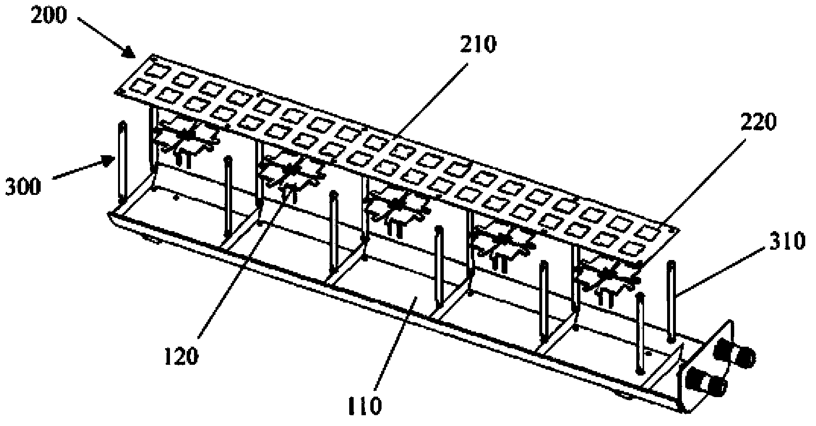
[0050] figure 1 is a schematic diagram of the overall structure of the base station antenna according to the first embodiment of the present invention. The base station antenna of the first embodiment includes a plurality of radiation elements 120 , a reflection plate 110 , a metamaterial plate and a supporting device 300 . , the reflecting plate 110 is used to reflect electromagnetic waves, and each radiation unit 120 is installed on the reflecting plate 110 . The metamaterial plate 200 and the reflection plate 110 are respectively located on two sides of each radiation unit 120 . The metamaterial plate 200 includes a dielectric substrate 210 and a plurality of microstructure units 220 of the same size and structure regularly arranged on the first surface and the second surface of the dielectric substrate 210 . The first surface and the second surface of the dielectric substrate 210 are opposite to each other and parallel to the reflection plate 110 . In this embodiment, t...
no. 2 example
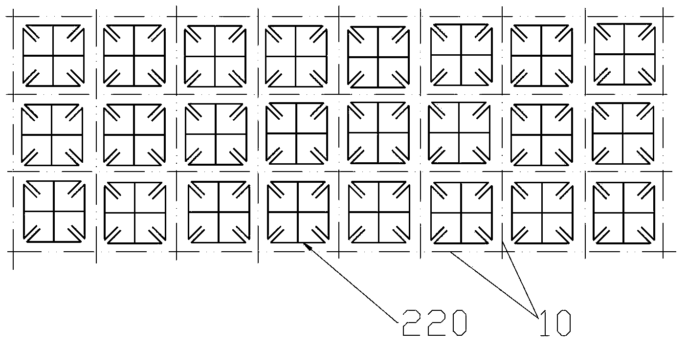
[0078] Figure 9 is a schematic diagram of the topological structure of the metamaterial plate 200 in the base station antenna according to the second implementation of the present invention.
[0079] In the second embodiment, the specific structure of the microstructure unit 220 is the same as that of the first embodiment. The main difference between the second embodiment and the first embodiment lies in the arrangement of the microstructure units. Such as Figure 9 As shown, a plurality of microstructure units 220 located on the same surface of a dielectric substrate 210 are arranged in such a way that the surface is divided into a plurality of grids by a plurality of imaginary straight lines 10, wherein each line segment forming each grid corresponds to One microstructure unit 220 is set, and the center of each microstructure unit 220 coincides with the midpoint of the corresponding line segment. Each side of the square where the outer contour of the microstructure unit ...
no. 3 example
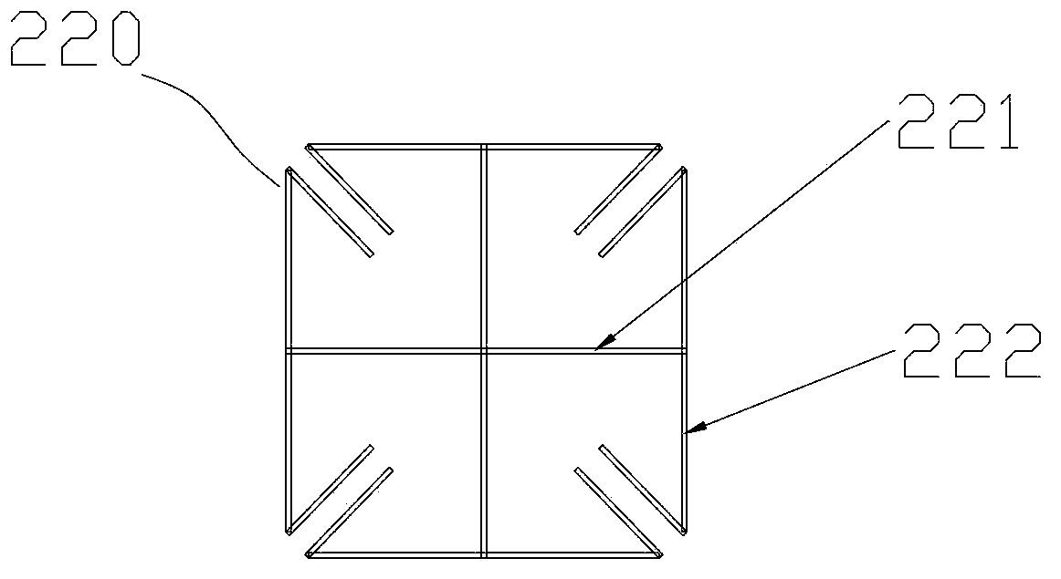
[0082] Figure 10 It is a schematic diagram of the topological structure of the first surface microstructure unit 220 of the metamaterial plate 200 in the base station antenna according to the third implementation of the present invention.
[0083] In the third embodiment, the structure of the microstructure unit 220 is also the same as that of the first embodiment. The main difference between the third embodiment and the first embodiment lies in the arrangement of the microstructure units.
[0084] Such as Figure 10 As shown, in the third embodiment, a plurality of microstructure units 220 located on the same surface of a dielectric substrate 210 are arranged in such a way that the surface is divided into a plurality of squares by a plurality of imaginary straight lines 10, wherein each square One microstructure unit 220 is correspondingly arranged inside the grid, and the center of each microstructure unit 220 coincides with the center of the corresponding grid. At the s...
PUM
 Abstract
Description
Claims
Application Information