Antenna apparatus, atenna reflector and radio communication unit for introducing antenna

A technology of antenna reflector and antenna equipment, which is applied in the direction of mid-position feeding, antenna, resonant antenna and other directions between antenna endpoints, and can solve problems such as negative effects

Inactive Publication Date: 2007-07-25
SONY GRP CORP
View PDF1 Cites 6 Cited by
  • Summary
  • Abstract
  • Description
  • Claims
  • Application Information

AI Technical Summary

Problems solved by technology

If the front-to-back ratio is poor, the operation of circuit modules arranged behind the reflector tends to be negatively affected

Method used


Image

  • Antenna apparatus, atenna reflector and radio communication unit for introducing antenna
  • Antenna apparatus, atenna reflector and radio communication unit for introducing antenna
  • Antenna apparatus, atenna reflector and radio communication unit for introducing antenna

Examples


Embodiment Construction

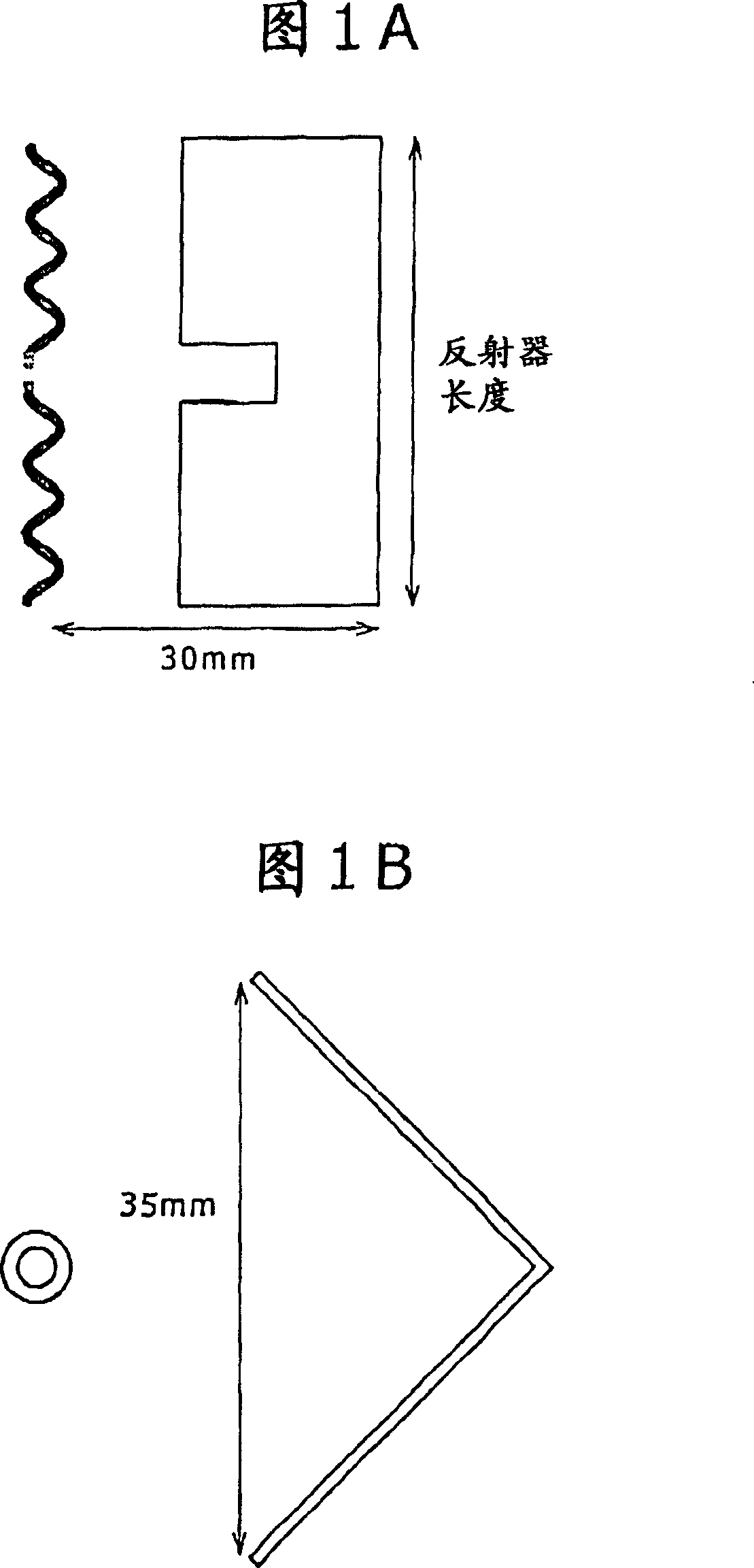
[0063] 1A to 1C show an antenna device according to an embodiment of the present invention. 1A and 1B are side and top views of the antenna device, respectively, and FIG. 1C is a perspective view of the antenna device. The antenna device is an endfire array antenna comprising a radiator and a reflector. The radiator comprises a helical dipole antenna, and the reflector comprises a corner reflector in the form of a conductor plate bent along the ridge at a predetermined angle Ψ (=90 degrees).

[0064] The distance between the helical dipole antenna and the corners of the corner reflector is a quarter of the wavelength λ used. A helical dipole antenna is used for linear polarization and is positioned such that the corners of the corner reflectors appear on the main plane of polarization of the helical dipole antenna.

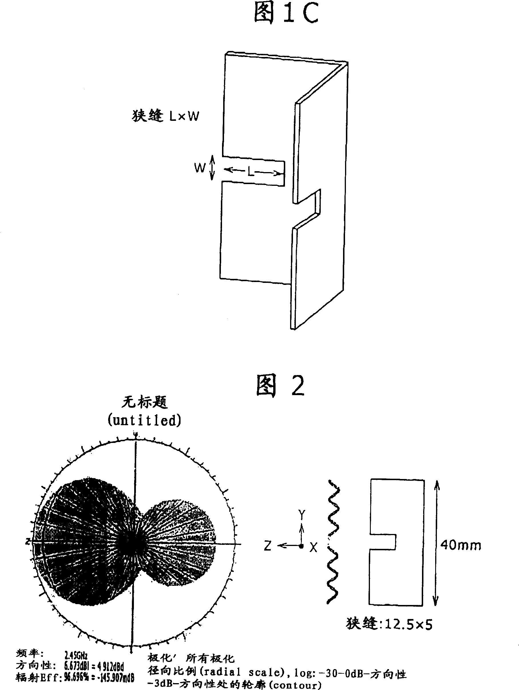
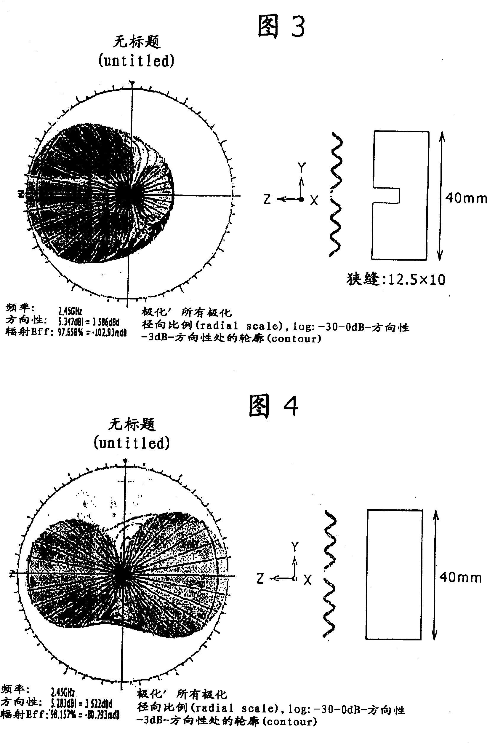
[0065] The corner reflector has two sides extending parallel to the main plane of polarization, and the two sides have respective slits defined thereon for incr...


PUM


Abstract

The invention discloses a antenna device, including a radiator having feeder wire, a flat reflector dividing along incident direction of radio wave and radiator, the reflector has at least one silt limited on its lateral border.

Description

[0001] References to related patent applications [0002] The present invention contains subject matter related to Japanese Patent Application JP 2006-011175 filed in the Japan Patent Office on Jan. 19, 2006, the entire content of which is hereby incorporated by reference. technical field [0003] The present invention relates to an antenna device having a radiator and a reflector for mixing radio waves arriving from an incident direction and reflected waves from the reflector with each other through the radiator and receiving the mixed radio waves, and also relates to an antenna reflector As well as a wireless communication unit incorporating an antenna therein, the present invention particularly relates to an antenna device using a planar reflector for achieving high directivity, an antenna reflector, and a wireless communication unit incorporating an antenna therein. [0004] More particularly, the present invention relates to an antenna device having a high front-to-rear r...

Claims


Application Information

Patent Timeline
Patent Type & Authority Applications(China)
IPC IPC(8): H01Q19/10H01Q19/185H01Q15/18H01Q9/00H01Q9/16
CPCH01Q9/27H01Q1/362H01Q19/108
Inventor 朝仓健二横木清忠
Owner SONY GRP CORP
Why Eureka
Try Eureka