Antenna array and multi-port antenna

An antenna array and antenna technology, which is applied to antenna arrays, antennas, antenna unit combinations with different polarization directions, etc., can solve the problems of increasing antenna width, reducing antenna gain, and deteriorating polarization isolation, so as to improve gain , the effect of improving symmetry

Active Publication Date: 2018-10-23
WUHAN HONGXIN TELECOMM TECH CO LTD
View PDF9 Cites 5 Cited by
  • Summary
  • Abstract
  • Description
  • Claims
  • Application Information

AI Technical Summary

Problems solved by technology

However, the distance between the first radiating unit and the second radiating unit determines the width of the antenna. If the distance between two identical dipoles fed in parallel is increased, the width of the antenna will be increased, which is not conducive to the miniaturization of the antenna.
In addition, the gain of the antenna will be lower than that of the antenna with the same length

Method used


Image

  • Antenna array and multi-port antenna
  • Antenna array and multi-port antenna
  • Antenna array and multi-port antenna

Examples


Embodiment 1

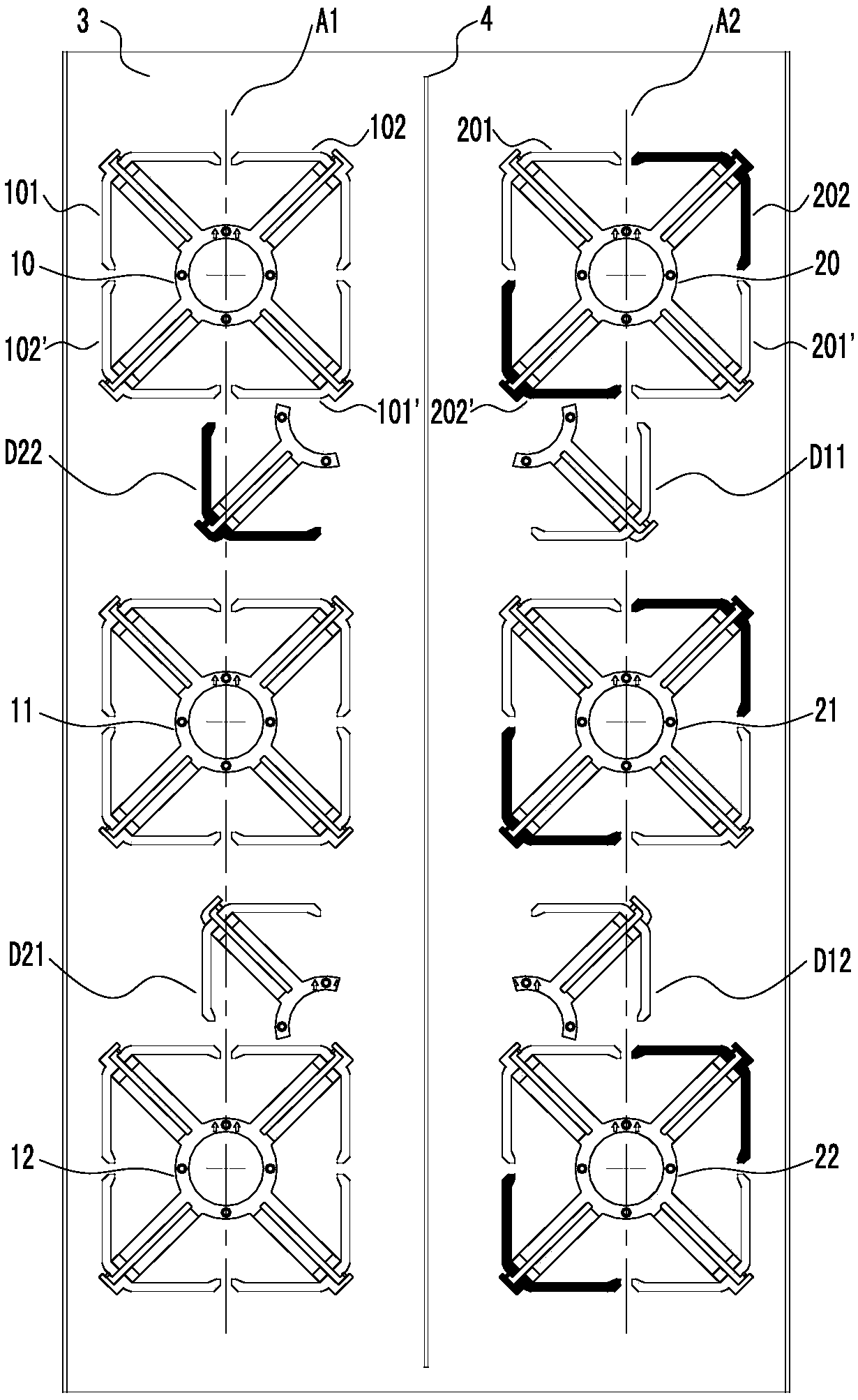
[0033] see figure 1 , in this embodiment, the antenna array includes at least two radiating element arrays, and the column axes are A1 and A2 respectively. The radiation units in the first column include but are not limited to 10, 11, and 12 three dual-polarized radiation units. The second row of radiation units includes but not limited to 20, 21, 22 three dual-polarized radiation units. The tenth radiating element consists of two pairs of orthogonally polarized dipoles. Preferably, the 101 and 101' dipoles form the +45° polarization of the tenth radiating unit, and the 102 and 102' dipoles form the -45° polarization of the tenth radiating unit.

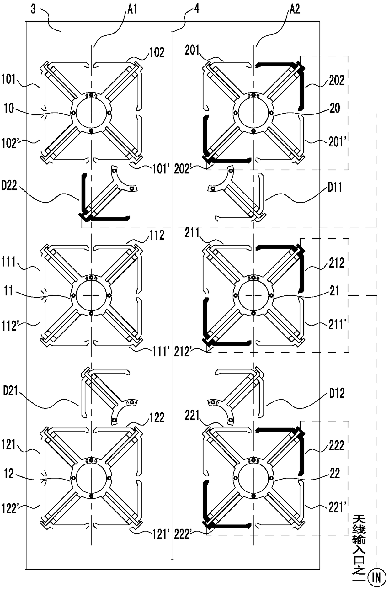
[0034] Such as figure 2As shown, the dotted line indicates the feed network connection of the right column of the antenna with -45° polarization. The pair of dipoles 202, 202' in the A2 array, the other pair of dipoles 212, 212', and the other pair of dipoles 222, 222' are fed in parallel, and the parallel feed is nested in D22 ...

Embodiment 2

[0041] The antenna array of this embodiment is similar to Embodiment 1, the difference is that:

[0042] Such as Figure 4 As shown, the pair of dipoles 202, 202' in the A2 array, the other pair of dipoles 212, 212', and the other pair of dipoles 222, 222' are fed in parallel, and the parallel feed is nested and arranged in the A1 array Inside the D22 dipole, the seven dipoles are connected through the feed network to form the right column of the antenna with -45° polarization. The position of the nested dipole D22 is between the radiation units 11 and 12 in the column A1; and the position of the nested dipole D22 in column A1 is between the radiation units 10 and 11 in the column A1. Obviously, nested dipole positions can be flexibly adjusted within adjacent columns.

Embodiment 3

[0044] The antenna array of this embodiment is similar to Embodiment 1, the difference is that:

[0045] Such as Figure 5 As shown, the pair of dipoles 202, 202' in the A2 array, the other pair of dipoles 212, 212', and the other pair of dipoles 222, 222' are fed in parallel, and the parallel feed is nested and arranged in the A1 array D22, D22' dipoles inside, the eight dipoles are connected through the feed network to form the right column of the antenna with -45° polarization.

[0046] In the same way, by parallel feeding the pair of dipoles 201 and 201' in the A2 array, the other pair of dipoles 211 and 211', and the other pair of dipoles 221 and 221', the parallel feeding arrangement is nested in A1 The D21 and D21' dipoles in the array, the eight dipoles are connected through the feed network to form the +45° polarization of the right column of the antenna.

[0047] Similarly, the dipoles D11, D11' are fed in parallel with the dipoles 101, 101', 111, 111' and 121, 121...


PUM


Abstract

The invention discloses an antenna array and a multi-port antenna, which are used for simplifying the radiation element array of a multi-port antenna, and improving the radiation performance of the multi-port antenna. The antenna array comprises at least (N+1) radiation unit arrays, and each radiation unit array comprises at least M radiation units, wherein M and N are positive integers which aregreater than or equal to one. Each radiation unit array distributed along an axis and at least one dipole nested in the adjacent radiation unit array form a radiation unit array combination. Each radiation unit array distributed along an axis and the dipole nested in the adjacent radiation unit array are connected in parallel through a feed network for feed. According to the invention, the antennaarray achieves the miniaturization and light weight of the multi-port antenna, guarantees the performance indexes and enables an antenna to have higher engineering applicability and better engineering operability.

Description

technical field [0001] The invention relates to the technical field of mobile communication antennas, in particular to an antenna array and a multi-port antenna. Background technique [0002] With the rapid development of mobile broadband services, various applications such as video, VR, and Internet of Things emerge in an endless stream, and user traffic demand grows rapidly. Facing the huge demand for capacity, operators have responded by acquiring new spectrum, improving spectrum efficiency, increasing site density, and other innovative technologies, so antennas that are closely related to this need continuous innovation. Facing the future, base station antennas will evolve towards multi-frequency and multi-port, multi-standard converged networking, miniaturization, and intelligence. A single antenna needs to support more spectrum and channels, better MIMO performance, and satisfy smooth network evolution. [0003] At present, solutions to realize multi-frequency, multi...

Claims


Application Information

Patent Timeline
IPC IPC(8): H01Q21/00H01Q21/24H01Q5/50H01Q19/10H01Q1/50
CPCH01Q1/50H01Q5/50H01Q19/10H01Q21/0006H01Q21/24
Inventor 梁超熊南金滕康平胡成军程伟
Owner WUHAN HONGXIN TELECOMM TECH CO LTD
Why Eureka
Try Eureka