Light-weight low-voltage power supply X-ray generating device

A low-voltage power supply and generating device technology, which is applied in the field of X-ray detection, can solve the problems of increasing the volume of the fuel tank, difficulty in miniaturizing the equipment, and increasing the volume and weight of the X-ray generating device, and achieves the effect of reducing weight and improving symmetry.

Inactive Publication Date: 2020-08-07
SHANTOU INST OF UITRASONIC INSTR CO LTD
View PDF7 Cites 0 Cited by
  • Summary
  • Abstract
  • Description
  • Claims
  • Application Information

AI Technical Summary

Problems solved by technology

Moreover, each power conversion device is installed in the fuel tank, which will increase the required volume of the fuel tank, and a larger fuel tank requires more oil, thereby increasing the volume and weight of the X-ray generating device, which makes it difficult to make the equipment lightweight miniaturization

Method used


Image

  • Light-weight low-voltage power supply X-ray generating device
  • Light-weight low-voltage power supply X-ray generating device
  • Light-weight low-voltage power supply X-ray generating device

Examples


Embodiment 1

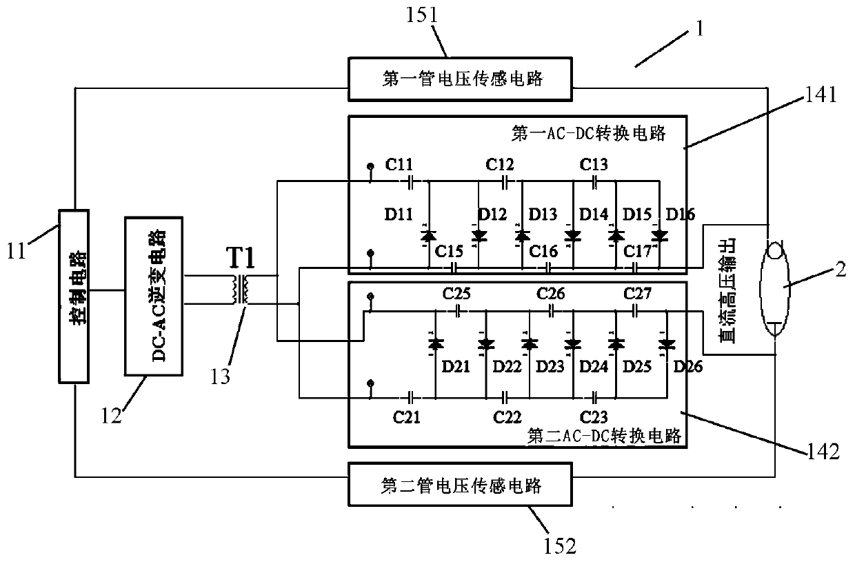
[0025] Embodiment 1: refer to figure 1 , a light-weight low-voltage power supply X-ray generating device, including a power supply circuit 1, an X-ray tube 2, a filament transformer 3 and an oil tank 4, and the power supply circuit 1 includes a control circuit 11, a DC-AC inverter circuit 12, and a step-up transformer 13. The first AC-DC conversion circuit 141 and the second AC-DC conversion circuit 142, the control circuit 11 is driven and connected to the DC-AC inverter circuit 12, and the DC-AC inverter circuit 12 is connected to an external power supply and the output is connected to a step-up transformer 13. The first AC-DC conversion circuit 141 and the second AC-DC conversion circuit 142 are circuits with mutually symmetrical functions and are connected in parallel to the output end of the step-up transformer 13; the X-ray tube 2 is connected to the first AC-DC conversion circuit. between the output terminal of the circuit 141 and the output terminal of the second AC-DC...

Embodiment 2

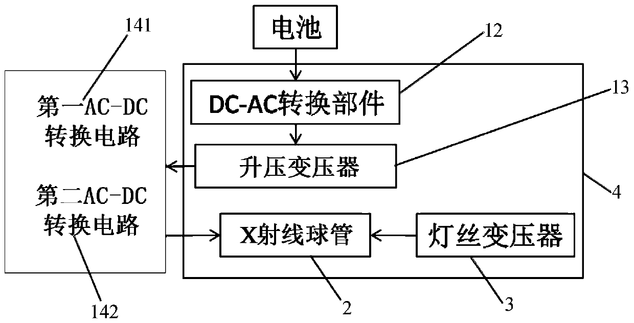
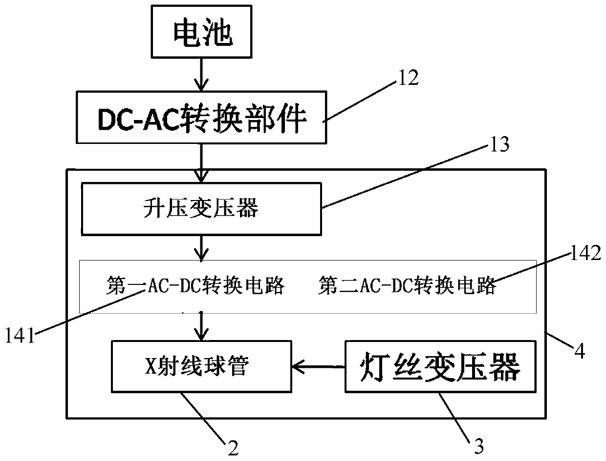
[0031] Embodiment 2, with reference to Figure 3-4 , In this embodiment, the difference from the embodiment is that: the first AC-DC conversion circuit 141 and the second AC-DC conversion circuit 142 are arranged in the fuel tank 4 . The first AC-DC conversion circuit 141 and the second AC-DC conversion circuit 142 are arranged in the oil tank 4 and are insulated and radiated by the oil in the oil tank 4. Specifically, the first AC-DC conversion circuit 141 and the second AC - The DC conversion circuit 142 is arranged separately and symmetrically in the oil tank 4, preferably, the first AC-DC conversion circuit 141 and the second AC-DC conversion circuit 142 can be respectively arranged on both sides of the step-up transformer 13 located in the middle of the oil tank 4 , so that the arrangement of components in the fuel tank 4 is more compact, the overall volume of the device is reduced, and the distance between the first AC-DC conversion circuit 141 and the second AC-DC conve...

Embodiment 3

[0032] Embodiment 3, with reference to Figure 5 , this embodiment is based on Embodiment 2, and the DC-AC inverter circuit 12 is connected to the oil in the oil tank 4 through the heat conduction mechanism 7 . Specifically, the heat conduction mechanism 7 includes a heat conduction seat 71 and a plurality of cooling fins 72 integrally connected with the heat conduction seat 71, the plurality of heat dissipation fins 72 are arranged in the fuel tank 4, the heat conduction seat 72 is arranged outside the fuel tank 4, and the DC-AC inverter circuit 12 is fixed Set on the heat conduction seat 72 . The DC-AC inverter circuit 12 is connected to the oil in the oil tank 4 through the heat conduction mechanism 7, and the oil in the oil tank 4 can be used to dissipate heat from the DC-AC inverter circuit 12, thereby eliminating the need for the DC-AC inverter circuit 12 The unique heat dissipation mechanism further reduces the volume and weight of the device, achieving a lightweight e...


PUM


Abstract

The invention relates to the technical field of X-ray detection, in particular to a light-weight low-voltage power supply X-ray generation device. The device comprises a power supply circuit, an X-raybulb tube, a filament transformer and an oil tank, the power supply circuit comprises a control circuit, a DC-AC inverter circuit, a boosting transformer, a first AC-DC conversion circuit and a second AC-DC conversion circuit. The control circuit is in driving connection with the DC-AC inverter circuit, the DC-AC inverter circuit is connected with an external power supply and is in output connection with the boosting transformer, and the first AC-DC conversion circuit and the second AC-DC conversion circuit are circuits with mutually symmetrical functions and are connected to the output end of the boosting transformer in parallel; the X-ray bulb tube is connected between the output end of the first AC-DC conversion circuit and the output end of the second AC-DC conversion circuit. One boosting transformer is adopted to be connected with two symmetrical AC-DC conversion circuits at the same time to supply power to the X-ray bulb tube, one transformer can be omitted, and the weight of equipment is reduced.

Description

technical field [0001] The invention relates to the technical field of X-ray detection, in particular to a lightweight X-ray generator with low-voltage power supply. Background technique [0002] In X-ray photography, the X-ray tube needs high voltage to excite and generate X-rays, and in the application of low-voltage X-ray generators, a series of power conversion devices are needed to convert the low-voltage power supply into the high voltage required by the X-ray tube. piezoelectric. In the X-ray generating device, the DC-AC conversion part is used to convert direct current into high-frequency alternating current, the high-voltage transformer converts high-frequency alternating current into high-voltage alternating current, and the AC-DC conversion part converts high-voltage alternating current into direct current, and the direct current is supplied to X-rays The tube is used to generate X-rays, and the sensor component samples the tube voltage and tube current of the ra...

Claims


Application Information

Patent Timeline
IPC IPC(8): H05G1/32H05G1/10
CPCH05G1/10H05G1/32
Inventor 李德来苏树钿刘庚辛陈英怀陈图森
Owner SHANTOU INST OF UITRASONIC INSTR CO LTD
Why Eureka
Try Eureka