Ring laser gyroscope that does not require mirrors

a gyroscope and laser technology, applied in the field of gyroscopes, can solve the problems of high manufacturing cost, limited accuracy and durability of gyroscopes, and must be reflected in the total cost of gyroscopes

Active Publication Date: 2007-07-17
LITTON SYST INC +1
View PDF4 Cites 35 Cited by
  • Summary
  • Abstract
  • Description
  • Claims
  • Application Information

AI Technical Summary

Problems solved by technology

Although spinning wheel gyroscopes have been effective, such gyroscopes have limitations in accuracy and durability due to friction and mechanical aspects associated with the spinning wheel.
Producing the mirrors to such exacting standards results in high manufacturing costs that must be reflected in the total cost of the gyroscope.

Method used


Image

  • Ring laser gyroscope that does not require mirrors
  • Ring laser gyroscope that does not require mirrors

Examples


Embodiment Construction

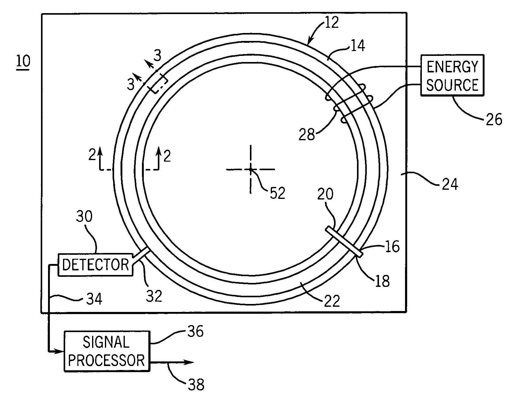
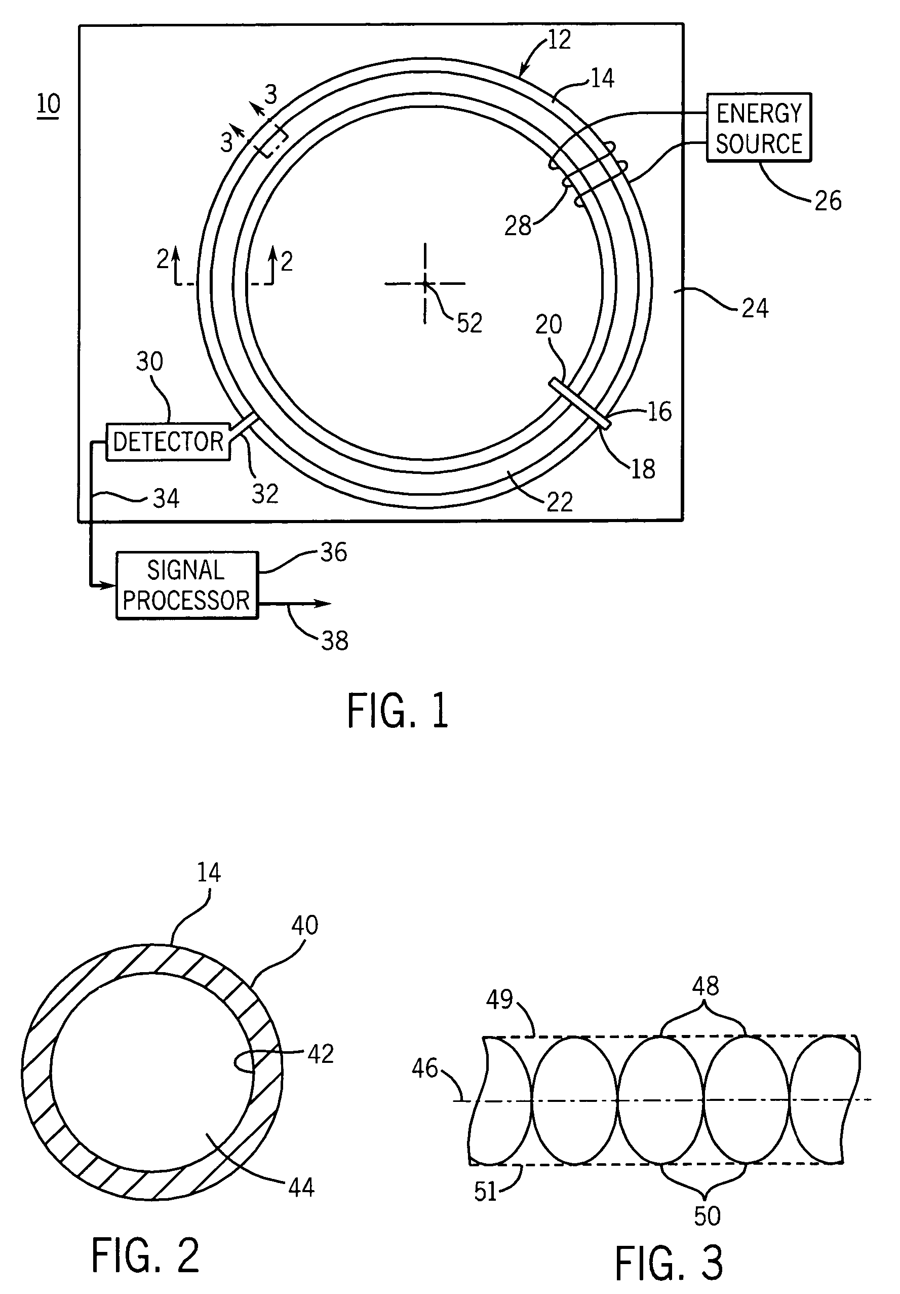
[0010]FIG. 1 shows an embodiment 10 of a ring laser gyroscope in accordance with the present invention. The ring 12 is preferably constructed of a hollow photonic bandgap fiber 14 and is shown in FIG. 1 as if it had been severed along its longitudinal centerline to better show that the interior is hollow. It will be understood that fiber 14 is actually a closed cylindrical elongated fiber. The ends 16 and 18 of the fiber 14 are coupled together by a splice 20 to create a closed configuration that defines a continuous, hollow passage 22. The purpose of the splice 20 is to connect the ends 16 and 18 of the fiber 14 together to form a continuous loop with a minimum of discontinuities being introduced by the splice. Before the ends 16 and 18 are coupled together, the passage 22 is filled, preferably completely, with a material, such as a gas, that will lase when excited by externally provided energy. For example, helium neon gas can be utilized and when excited produces a laser beam of ...


PUM


Abstract

In an embodiment of a ring laser gyroscope, a hollow bandgap fiber is filled with a gas or material that will generate laser beams within the fiber upon being excited by an energy source. A detector coupled to the fiber detects a standing wave pattern within the fiber, wherein changes in the detected standing wave pattern indicates a corresponding change in the orientation of the fiber.

Description

BACKGROUND[0001]This invention relates in general to gyroscopes and more specifically to ring laser gyroscopes.[0002]Navigational systems represent an important use of gyroscopes since it is important to know and / or maintain a specific orientation of a vehicle or movable device relative to another location or object. A gyroscope outputs information related its change in orientation and hence can determine the orientation of the vehicle to which it is mounted. This output information can be processed and displayed to provide a measurement of the orientation of the vehicle and can also be used as a feedback signal coupled to a propulsion system to maintain a specified orientation of the vehicle.[0003]Conventional gyroscopes with a spinning wheel make use of the effect of precession in which the spinning wheel maintains its orientation relative to the plane in which the wheel spends. Although spinning wheel gyroscopes have been effective, such gyroscopes have limitations in accuracy an...

Claims


Application Information

Patent Timeline
Patent Type & Authority Patents(United States)
IPC IPC(8): G01C19/64
CPCG01C19/64G01C19/72
Inventor MARINO, KENNETHTAZARTES, DANIEL A.VOLK, CHARLES
Owner LITTON SYST INC
Why Eureka
Try Eureka