Circuit arrangement and method for controlling a bistable magnetic valve

a bistable magnetic valve and circuit arrangement technology, applied in the direction of electric control, magnetic bodies, machines/engines, etc., can solve the problems of limited injection process at high engine speed, additional, expensive heat dissipation methods to be used, etc., and achieve the effect of low power dissipation and greater switching times

Inactive Publication Date: 2007-07-17
CONTINENTAL AUTOMOTIVE GMBH
View PDF13 Cites 14 Cited by
  • Summary
  • Abstract
  • Description
  • Claims
  • Application Information

AI Technical Summary

Benefits of technology

[0020]Accordingly one of the objects of the present invention is to remedy the disadvantages described above and especially to create a circuit arrangement as well as a method for controlling a bistable magnetic valve which make low power dissipation possible or, for a specific power dissipation, allow greater switching times.
[0021]This object can be achieved by a circuit arrangement to control a bistable magnetic valve in which a magnetic coil is to be supplied with an electrical current pulse to switch the magnetic valve from a first stable valve state into a second stable valve state, comprising a power supply source to provide a supply voltage, a power supply device fed by the power supply source and able to be activated for the duration of the current pulse by an entered control signal to create a coil current flowing through the magnetic coil, wherein the coil current being set to a setpoint, and changeover means to reduce the setpoint of the coil current during the current pulse.

Problems solved by technology

With high pressure diesel systems (“Common Rail”) with multiple injections for example, this limits the number of injection processes possible at high engine speeds.
In a similar way the power dissipation produced in a valve controller using these types of magnetic valve also represents a technical challenge which often forces additional, expensive heat dissipation methods to be used.

Method used


Image

  • Circuit arrangement and method for controlling a bistable magnetic valve
  • Circuit arrangement and method for controlling a bistable magnetic valve
  • Circuit arrangement and method for controlling a bistable magnetic valve

Examples


Embodiment Construction

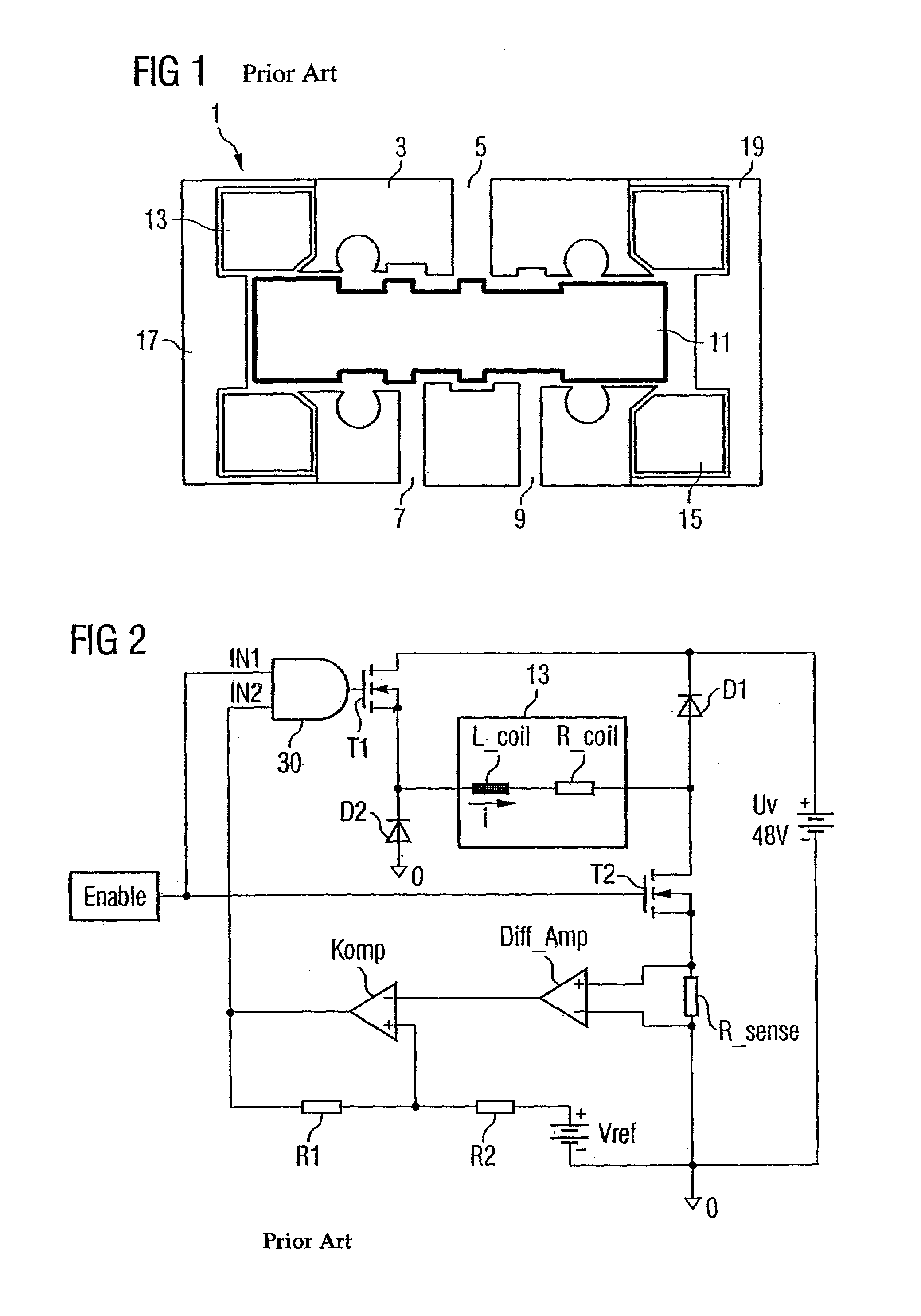
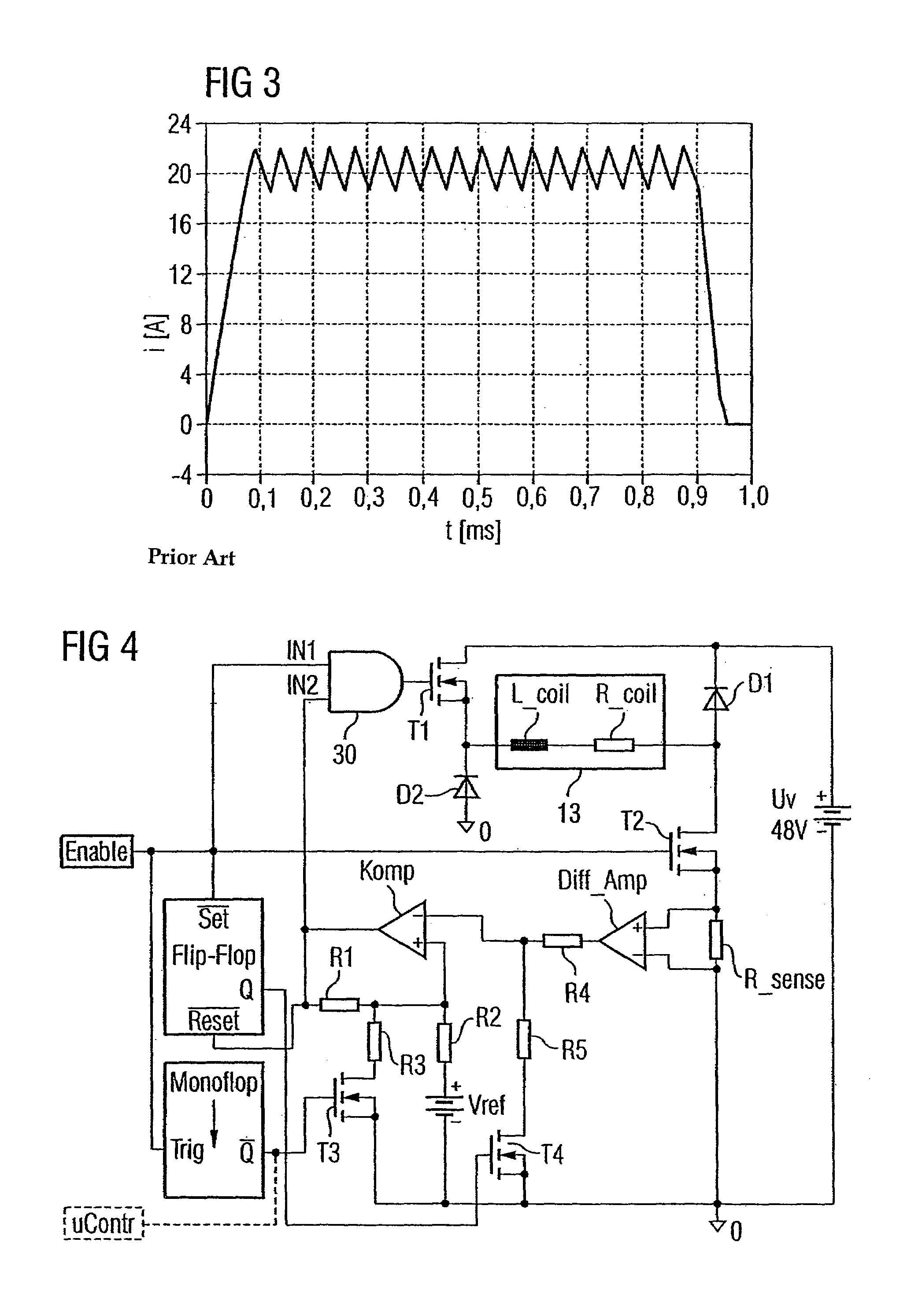
[0053]FIGS. 1, 2 and 3 show a conventional magnetic valve, a control circuit for this and also the timing curve of the coil current generated with this circuit for the duration of a current pulse to switch over the magnetic valve. These Figures have already been described in detail above and represent the point of departure for the exemplary embodiment of a circuit arrangement in accordance with the invention described below. In this subsequent description only the differences to the circuit arrangement already described (FIG. 2) or the current curve produced by it (FIG. 3) are described and otherwise the reader is explicitly referred to this previous description.

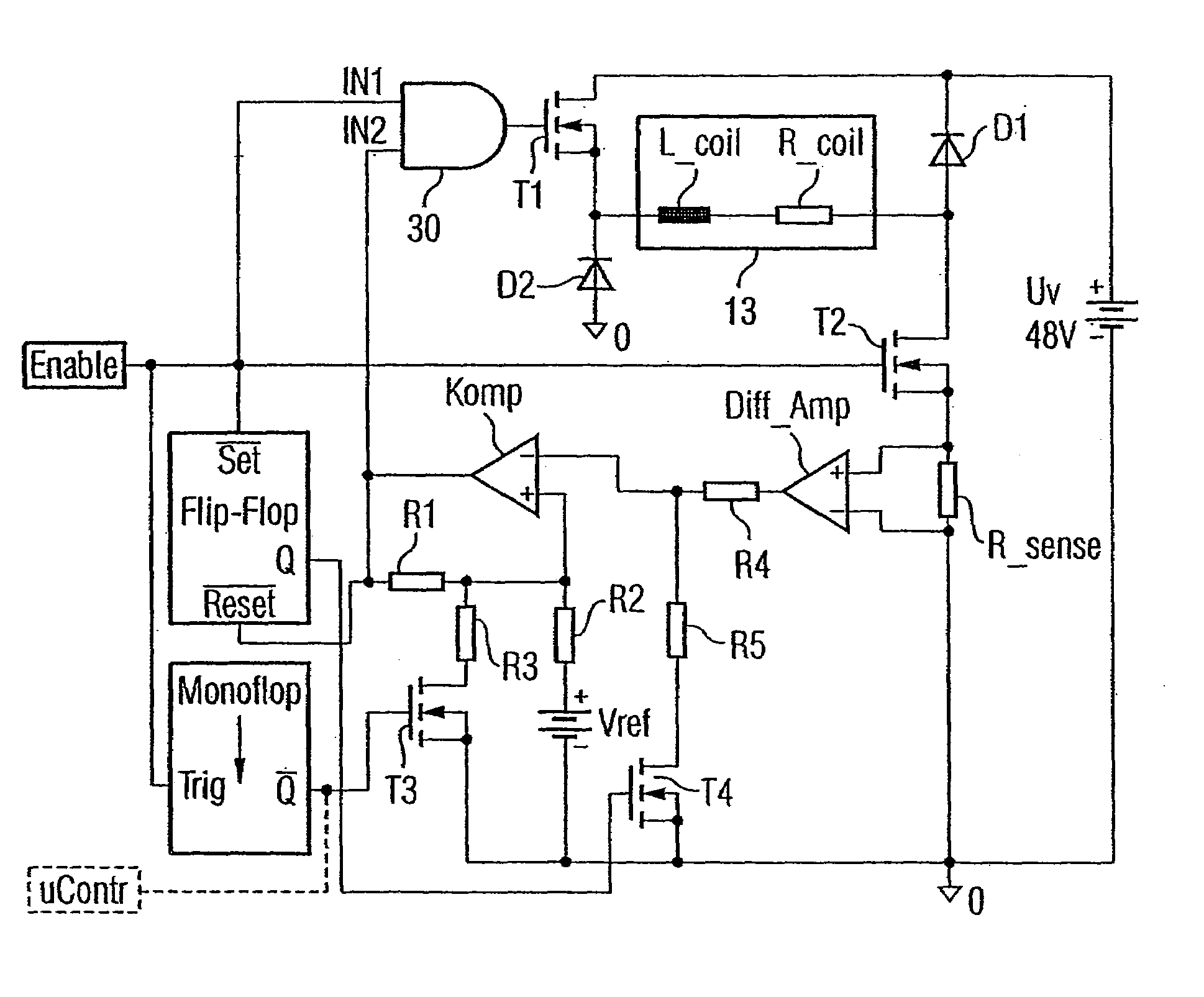
[0054]The circuit shown in FIG. 4 essentially functions like the circuit already described with reference to FIG. 2. In particular there is again a regulation of the coil current by a differential amplifier Diff_Amp and a comparator Komp, in which case the duration of the desired current pulse is again defined by a high lev...


PUM

PropertyMeasurementUnit
output voltageaaaaaaaaaa
voltageaaaaaaaaaa
voltageaaaaaaaaaa

Abstract

A circuit arrangement and also a method for controlling a bistable magnetic valve in which a magnetic valve is to be supplied with a pulse of electrical current in order to switch over the magnetic valve from a first stable state into a second stable state, comprises a power supply source to provide a supply voltage, a power supply device fed by the power supply source and able to be activated for the duration of the current pulse by an entered control signal (Enable) to create a coil current (I) flowing through the magnetic coil, with the coil current (I) being set to a setpoint, where changeover means are provided in order to reduce the setpoint of the coil current during the current pulse. This advantageously allows the power dissipation of the activation of bistable magnetic valves to be reduced.

Description

PRIORITY[0001]This application claims priority to German application no. 103 15 282.2 filed Apr. 3, 2003.TECHNICAL FIELD OF THE INVENTION[0002]The present invention relates to a circuit arrangement and also a method for controlling a bistable magnetic valve in which a magnetic valve is to be supplied with a pulse of electrical current in order to switch over the magnetic valve from a first stable valve state into a second stable valve state. The outstanding feature of such bistable magnetic valves is that in the stable state they do not require any control current but merely require a control current (current pulse) on switchover.BACKGROUND OF THE INVENTION[0003]Bistable magnetic valves are for example used in rapid-switching hydraulic actors and hydraulically-assisted servo valves in motor vehicles. A magnetic valve used for the opening and closing a hydraulic passage can in this case be held in a relevant end position by magnetic remanence forces of a flow line part (yoke). To kee...

Claims


Application Information

Patent Timeline
Patent Type & Authority Patents(United States)
IPC IPC(8): H01H47/32F16K31/06H01F7/18
CPCF16K31/0679H01F7/1805F02D41/20H01F7/1811H01F7/1844H01F2007/1669H01F2007/1692
Inventor BOLZ, STEPHANLUGERT, GUNTER
Owner CONTINENTAL AUTOMOTIVE GMBH
Why Eureka
Try Eureka