Circuit board fixer structure

a technology of fixing structure and circuit board, which is applied in the direction of support structure mounting, electrical apparatus construction details, casing/cabinet/drawer, etc., can solve the problems of troublesome and time-consuming implementation, circuit board b>12/b> may be damaged by coupling members, adversely affecting the performance of circuit board b, etc., to achieve the effect of easy assembly and disassembly of the stud

Inactive Publication Date: 2007-07-17
INVENTEC CORP
View PDF12 Cites 13 Cited by
  • Summary
  • Abstract
  • Description
  • Claims
  • Application Information

AI Technical Summary

Benefits of technology

[0014]The stud can be a cylinder or a cone, and is made of a plastic material. The stud has a handler portion for a user to easily assemble and disassemble the stud to and from the pillar. The handler portion can be a ring, a block, a wire, or an embossed and roughed surface formed on one end of the stud. One side of the stud can abut against a surface of the circuit board or can be spaced from the surface of the circuit board by a certain distance.
[0015]Therefore, the circuit board fixer structure of the present invention can solve the problems in the prior art such as inconvenient and time-consuming assembly and disassembly of a circuit board in an electronic device due to the use of screws to fix the circuit board in place.

Problems solved by technology

To fix the above circuit board 12 to the housing 13 of the electronic device needs a screwdriver or a similar tool to screw the coupling members 11, which is rather troublesome and time-consuming to implement.
If a force for screwing the coupling members 11 is not properly controlled, the circuit board 12 may be damaged by the coupling members 11.
Moreover, since the coupling members 11 are often made of a metallic material having electrical conductivity, they may cause signal interference to the circuit board 12, thereby adversely affecting the performance of the circuit board 12.
Moreover, the above design requires formation of the mounting hole 221 having the wide portion 2211 and the narrow portion 2212 for the circuit board 22, thereby undesirably increasing the fabrication cost.
Therefore, the problem to be solved here is to provide a circuit board fixer structure to overcome the foregoing drawbacks of the prior art.

Method used


Image

  • Circuit board fixer structure
  • Circuit board fixer structure
  • Circuit board fixer structure

Examples


first embodiment

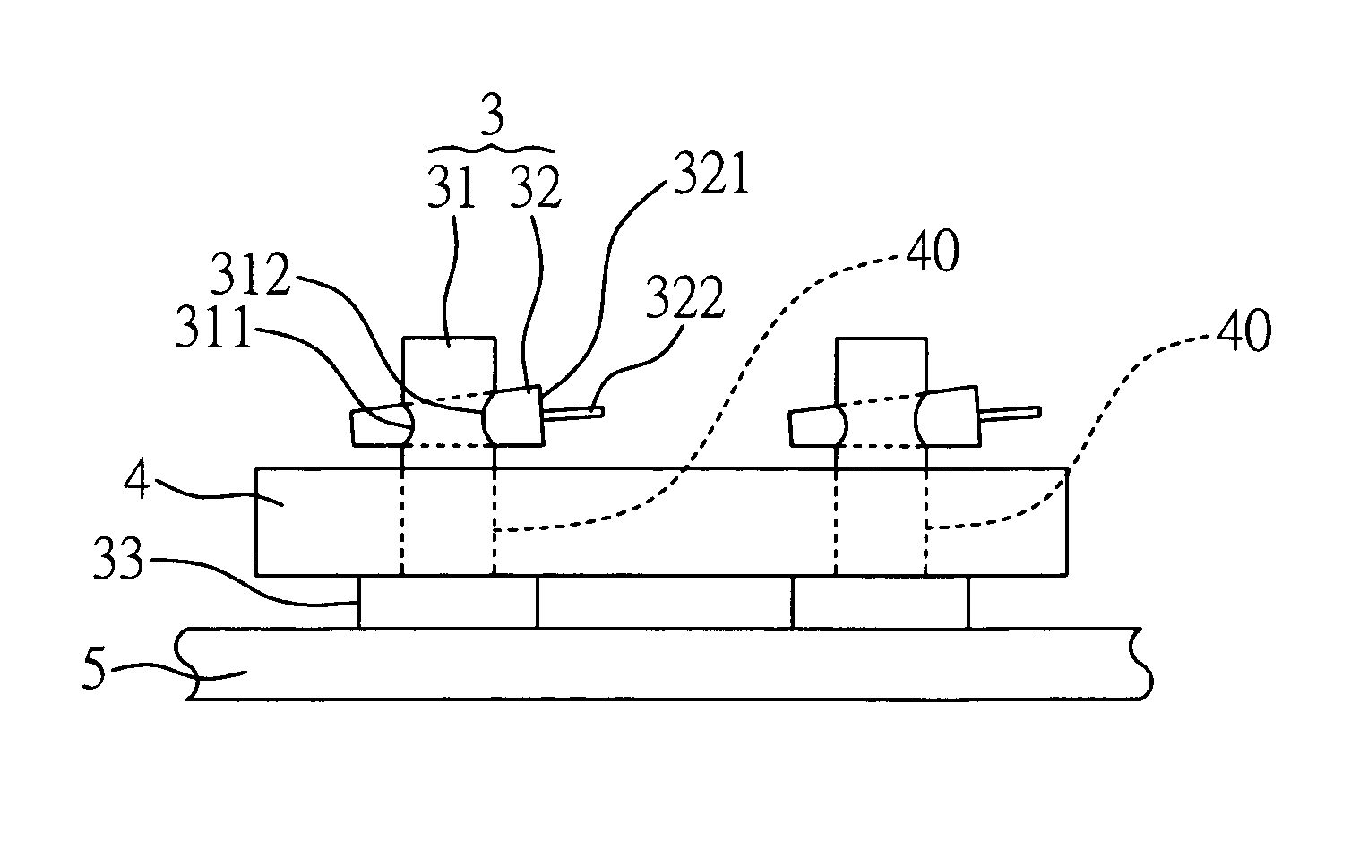
[0031]FIG. 4 shows the circuit board fixer structure 3 according to a second preferred embodiment of the present invention, wherein same or similar elements as compared with those of the first embodiment are denoted by same or similar reference numerals and are not further to be described in detail for the sake of brevity.

[0032]A primary difference of the circuit board fixer structure 3 of the second embodiment as compared with that of the first embodiment is in that, the end of the stud 32 is formed with an embossed surface 325 to replace and serve as the handler portion 322 of the first embodiment, so as to reduce the material and the cost. The embossed surface 325 provides the same effect as the handler portion 322 of the first embodiment, for the user to hold the embossed surface 325 to assemble and disassemble the stud 32 to and from the pillar 31.

second embodiment

[0033]FIG. 5 shows the circuit board fixer structure 3 according to a third preferred embodiment of the present invention, wherein same or similar elements as compared with those of the second embodiment are denoted by same or similar reference numerals and are not further to be described in detail for the sake of brevity.

[0034]A primary difference of the circuit board fixer structure 3 of the third embodiment as compared with that of the second embodiment is in that, the size of the first opening 311 is equal to that of the second opening 312 of the pillar 31, and the stud 32 is a cylinder to conform to such arrangement of the pillar 31. Moreover, a buffer ring 326 is provided between the stud 32 and the circuit board 4 to increase the friction of the stud 32 and avoid the stud 32 coming off, such that the stud 32 can be secured in position by means of the buffer ring 326. The buffer ring 326 can further absorb external shocks exerted to the circuit board 4, and is made of rubber.

[...


PUM


Abstract

A circuit board fixer structure, for fixing a circuit board having at least one through hole, includes a carrier for carrying the circuit board, a pillar, and a stud. The pillar is mounted on the carrier and is formed with a first opening and a second opening corresponding to the first opening. The circuit board is fixed in place on the carrier by the pillar penetrating the through hole of the circuit board and the stud penetrating the first and second openings of the pillar to be coupled to the pillar. By the circuit board fixer structure, there is no need to use any tool to assemble and disassemble a circuit board in an electronic device, making the assembly and disassembly of the circuit board convenient to implement.

Description

FIELD OF THE INVENTION[0001]The present invention relates to circuit board fixer structures, and more particularly, to a fixer structure for a circuit board of an electronic device.BACKGROUND OF THE INVENTION[0002]As the technology advances, electronic devices such as desktop computers, laptop computers and servers have played an important role in the daily life. Each electronic device is provided with a circuit board (or a motherboard) that is fixed to a housing of the electronic device. Various ways for fixing the circuit board to the electronic device are available and cause different effects on the circuit board.[0003]FIG. 1A is a top view of a conventional circuit board 12 mounted on a housing 13 of an electronic device, and FIG. 1B is a front view of the structure shown in FIG. 1A. As shown in FIGS. 1A and 1B, the housing 13 of the electronic device is formed with a plurality of carrier pads 131 thereon, wherein each of the carrier pads 131 has a blind hole 1311. The circuit b...

Claims


Application Information

Patent Timeline
Patent Type & Authority Patents(United States)
IPC IPC(8): H05K7/14
CPCH05K7/142
Inventor LUO, ZI-GUIMA, EVAFAN, BG
Owner INVENTEC CORP
Why Eureka
Try Eureka