Water feature
a technology of water feature and water emulsion, applied in the field of water feature, can solve the problems of affecting the display effect, and affecting the display effect, and achieve the effect of simple recovery and attractive visual
- Summary
- Abstract
- Description
- Claims
- Application Information
AI Technical Summary
Benefits of technology
Problems solved by technology
Method used
Image
Examples
first embodiment
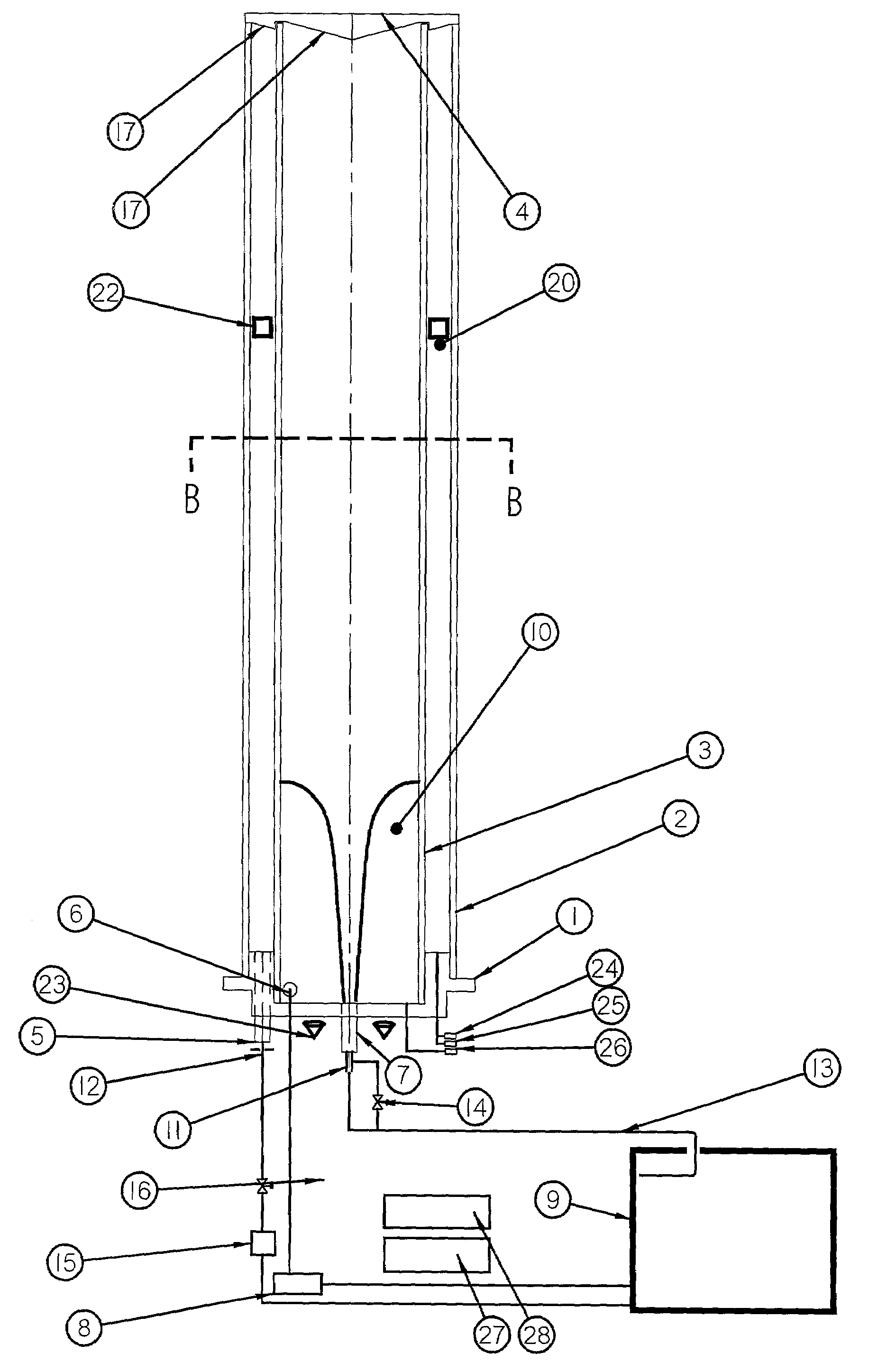
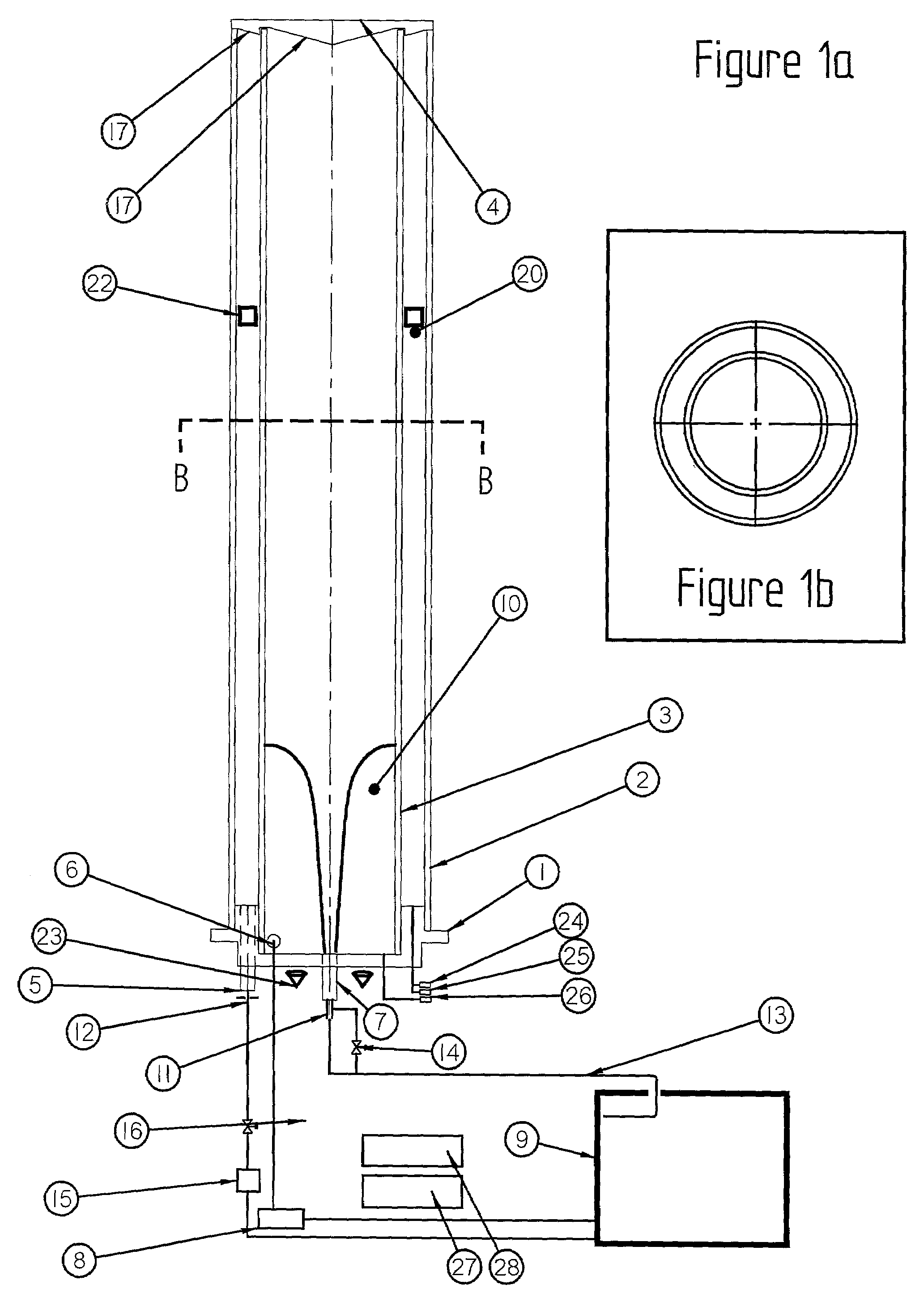
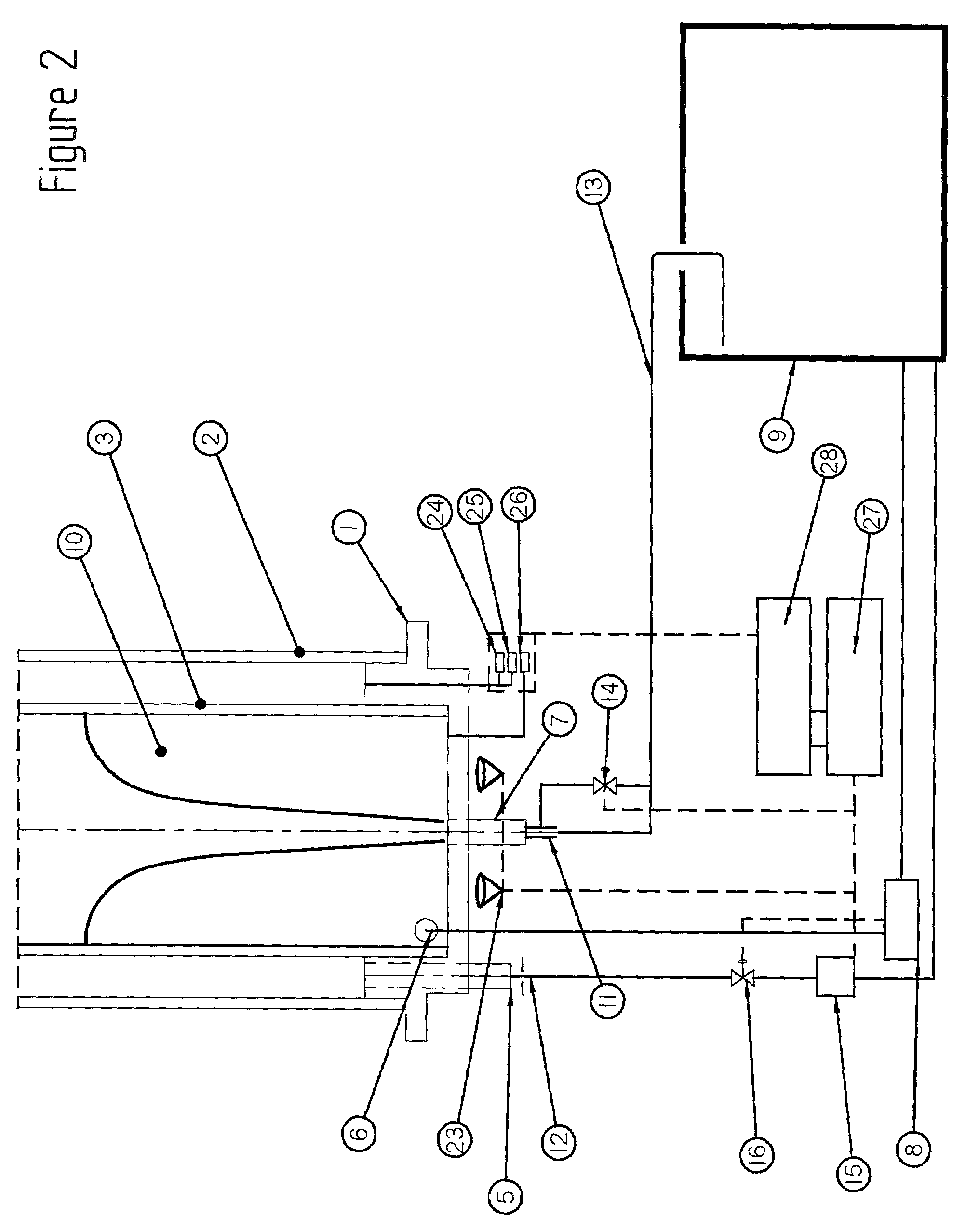
[0054]The first embodiment uses a centrifugal type pump for both the inner tube fill pump 8 and the outer tube fill pump 15. It is illustrated in FIGS. 1 to 3 and takes the form of a clock.
[0055]The main clock components are the manifold 1 connected and sealed to an outer tube 2, an inner tube 3 and a co-venting but outwardly sealed lid 4 which allows air to pass between the outer tube 2 and the inner tube 3. The manifold 1 has connections for an outer tube fill and drain port 5, an inner tube tangential fill port 6 and an inner tube drain port 7. Rigid or flexible conduits can be connected to these ports. Water which can be discharged through the inner tube tangential fill port 6 enters on the tangent to the inner wall of the inner tube 3. The inner tube drain port 7 is on the central axis of the inner tube 3. If water is pumped into the inner tube 3, through the inner tube tangential fill port 6 from an inner tube fill pump 8, which draws water from a sump 9 at a rate in excess of...
second embodiment
[0070]The action of the outer coaxial water column 20, in this second embodiment, clock is now described.
[0071]The outer coaxial water column 20, which can have an optional float 22 on top, is supplied from the outer tube fill pump 15. If the outer tube drain valve 16 is closed and the outer tube fill pump 15 is on, then the outer coaxial water column 20 will increase in height. The electronic control and timing means 27 and 28 ensure that, just past the start of a 12 hour cycle (12 noon or 12 midnight), the outer tube drain valve 16 is closed and the outer tube fill pump is switched on. The outer tube fill pump 15 can be controlled to deliver water such that the level of water in the volume 20 increases from a low level to a high level over 12 hours. At the end of the 12 hour cycle, the outer tube fill pump 15 is switched off, the outer tube drain valve 16 is opened and the water drains back to the sump 9. After the empty cycle, just into the start of the new 12 hour period, the ou...
third embodiment
[0072]The third embodiment uses one centrifugal type pump between both columns. It is illustrated in FIGS. 6 and 7 and also takes the form of a clock. FIGS. 1b and 3 also apply to this embodiment.
[0073]In the two previously described embodiments, two pumps are used to supply water to the clock. The inner tube fill pump 8 supplies flow to create the vortex of water 10 and the outer tube fill pump 15 (which could either be a dosing or centrifugal pump) supplies flow to the outer coaxial water column 20.
[0074]In this further embodiment now described, the inner tube fill pump 8 (which is a centrifugal type pump) is used alternately to provide a flow of water for the vortex of water 10 and the outer coaxial water column 20.
[0075]The outer tube fill pump 15 is not required. A three way divertor valve 29 is now fitted after the inner tube fill pump 8. The operation of this single-pump embodiment of the clock is now described from the start of a new 12 hour period. For this description, it ...
PUM
 Abstract
Description
Claims
Application Information
 - R&D
- Intellectual Property
- Life Sciences
- Materials
- Tech Scout
- Unparalleled Data Quality
- Higher Quality Content
- 60% Fewer Hallucinations
Browse by: Latest US Patents, China's latest patents, Technical Efficacy Thesaurus, Application Domain, Technology Topic, Popular Technical Reports.
© 2025 PatSnap. All rights reserved.Legal|Privacy policy|Modern Slavery Act Transparency Statement|Sitemap|About US| Contact US: help@patsnap.com


