
Method and apparatus of image forming capable of suitably controlling transfer characteristic

a technology of image forming and transfer characteristic, which is applied in the direction of electrographic process apparatus, printing, instruments, etc., can solve the problems of affecting the quality of image forming, and requiring a considerable amount of time for the process, and achieving the effect of avoiding color shift, avoiding color shift, and avoiding color shi

Inactive Publication Date: 2007-07-17
RICOH KK
View PDF11 Cites 8 Cited by
  • Summary
  • Abstract
  • Description
  • Claims
  • Application Information

AI Technical Summary

Benefits of technology

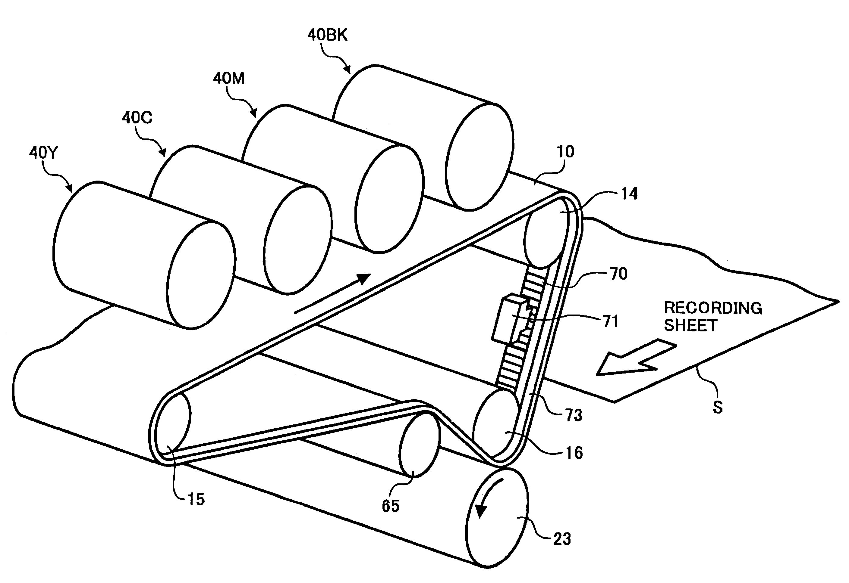
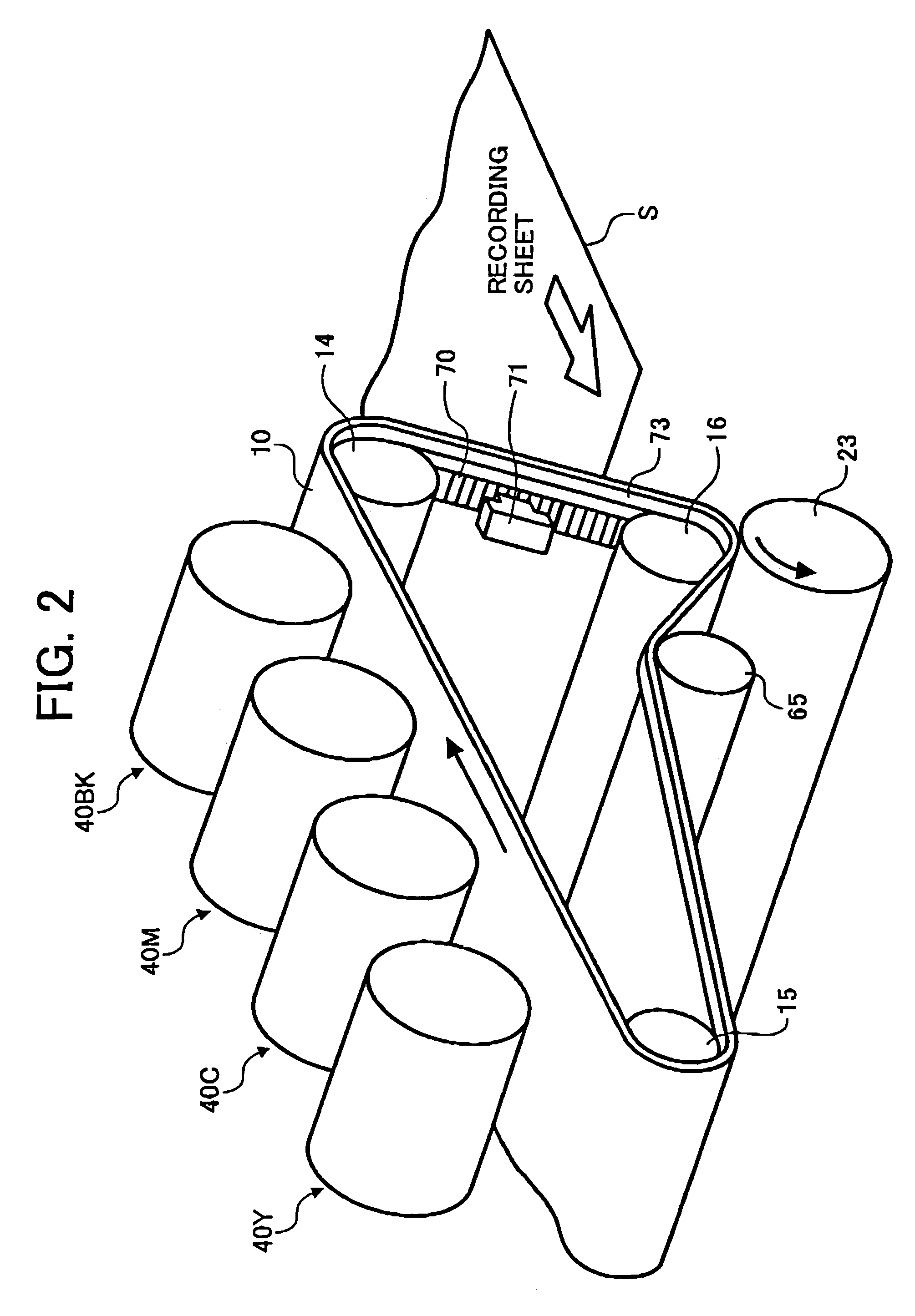
[0016]Under an exemplary embodiment, a novel image forming apparatus includes a rotating member, a drive mechanism, a scale, and a scale reading mechanism. The rotating member is configured to carry an image. The drive mechanism is configured to rotationally drive the rotating member. The scale is provided around an entire perimeter of a surface

Problems solved by technology

This process requires a considerable amount of time.
However, the plurality of photoconductors makes the device relatively larger and more expensive.
In the above mentioned systems, overlaying a plurality of color images of different colors (magenta, cyan, yellow and black toner images) on the transfer member without color shift is a significant challenge.
However, another problem arises.
When a rotating member is an endless belt, an end of the belt is often rippled or distorted.
Generally, tensioned endless belts tend to ripple at the end of the belts, causing loss in positional accuracy of liner encoders.
An additional problem is that a scale for measuring a speed by linear encoders often causes static electricity, thereby affecting images and sheet conveyance.
The above-mentioned problems also apply to the one drum type color image forming apparatus.
They become an impediment to enhancement of image quality.

Method used


Image

  • Method and apparatus of image forming capable of suitably controlling transfer characteristic
  • Method and apparatus of image forming capable of suitably controlling transfer characteristic
  • Method and apparatus of image forming capable of suitably controlling transfer characteristic

Examples


Embodiment Construction

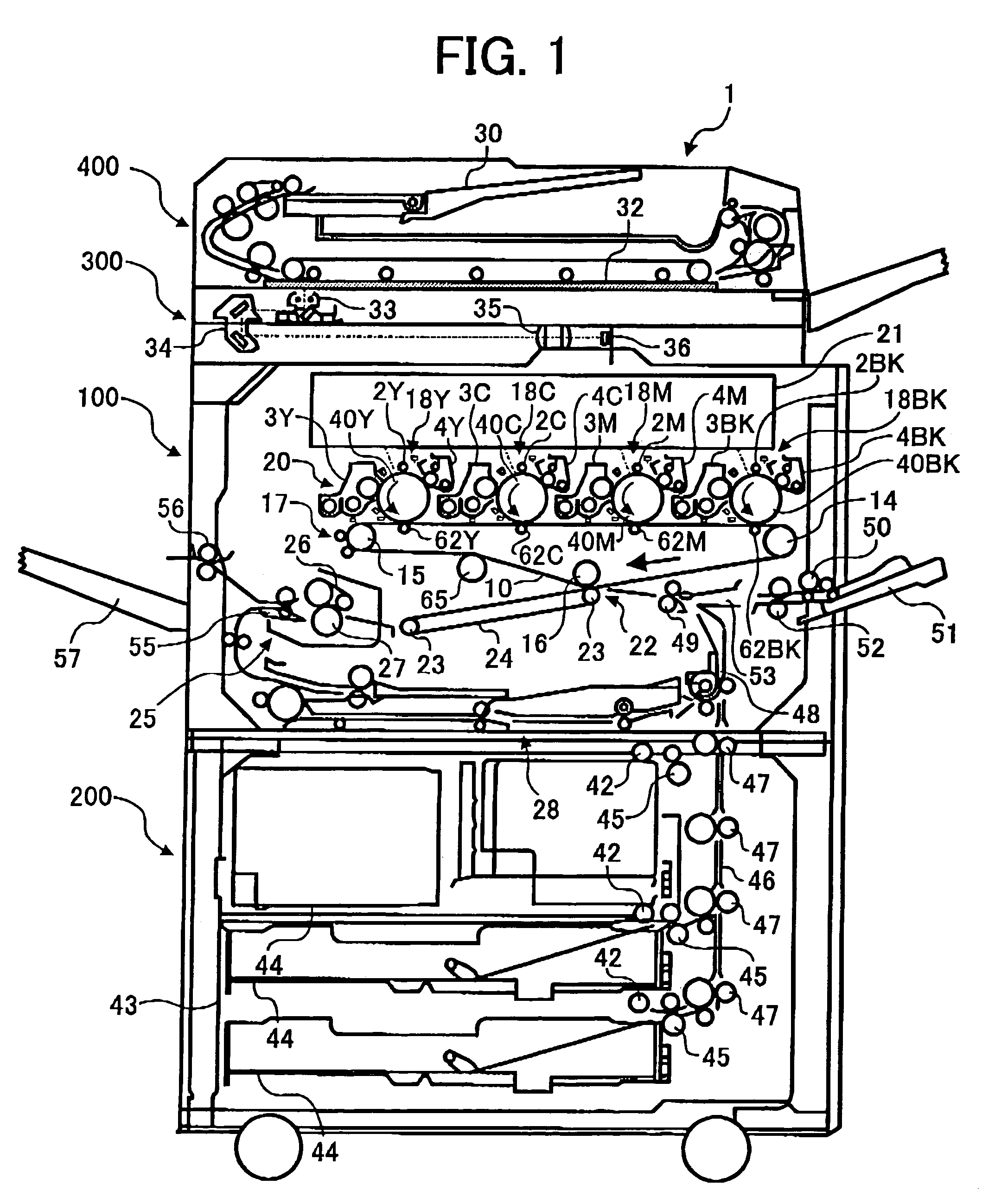
[0028]In describing preferred embodiments illustrated in the drawings, specific terminology is employed for the sake of clarity. However, the disclosure of this patent specification is not intended to be limited to the specific terminology so selected and it is to be understood that each specific element includes all technical equivalents that operate in a similar manner. Referring now to the drawings, wherein like reference numerals designate identical or corresponding parts throughout the several views, particularly to FIGS. 1 to 4, an exemplary tandem type color copy machine 1 according to a preferred embodiment of the present invention is now described.

[0029]FIG. 1 illustrates an exemplary structure and copying operation of the tandem type color copy machine 1 using an indirect transfer system.

[0030]The color copy machine 1 includes a color copying engine or assembly 100, a sheet feeding table 200 having the color copying engine 100 thereon, a scanner 300 provided on an upper su...


PUM


Abstract

An image forming apparatus includes a rotating member, a drive mechanism, a scale, and a scale reading mechanism. The rotating member is configured to carry an image. The drive mechanism is configured to rotationally drive the rotating member. The scale is provided around an entire perimeter of a surface of the rotating member. The scale reading mechanism is configured to read the scale and arranged in a region where the rotating member is prevented from wavering or being distorted. A rotating drive of the rotating member is controlled based on information read by the scale reading mechanism.

Description

CROSS-REFERENCE TO RELATED APPLICATIONS[0001]This patent specification is based on Japanese patent application no. 2002-370036, filed on Dec. 20, 2002, in the Japanese Patent Office, the disclosure of which is incorporated by reference herein in its entirety.BACKGROUND OF THE INVENTION[0002]1. Field of the Invention[0003]The present invention relates to an image forming apparatus, such as a copy machine, a printer, a facsimile, and a plotter, and more particularly to the image forming apparatus having a rotatable transfer member capable of stably transferring an image on an image carrier by eliminating a variation in a transfer characteristic.[0004]2. Discussion of the Related Art[0005]Many electrophotographic devices, such as a color copy machine and a color printer, have a function of printing a color image.[0006]Color electrophotographic devices can be generally classified as a one drum type and a tandem type. The one drum type includes a plurality of color developing devices dis...

Claims


Application Information

Patent Timeline
IPC IPC(8): G03G15/01G03G15/00G03G15/16
CPCG03G15/1605G03G15/5008G03G2215/00075G03G2215/00156G03G2215/0119
Inventor KAMIYA, TAKUROH
Owner RICOH KK
Learn More