
Snap electrode

a technology of snap electrodes and electrodes, which is applied in the field of snap electrodes, can solve the problems of many patients and/or practitioners avoiding the use of appropriate medical electrodes, hot spots touching the skin of patients, etc., and achieves the effect of more robust electrical connection

Active Publication Date: 2007-07-17
KPR U S LLC
View PDF11 Cites 15 Cited by
  • Summary
  • Abstract
  • Description
  • Claims
  • Application Information

AI Technical Summary

Benefits of technology

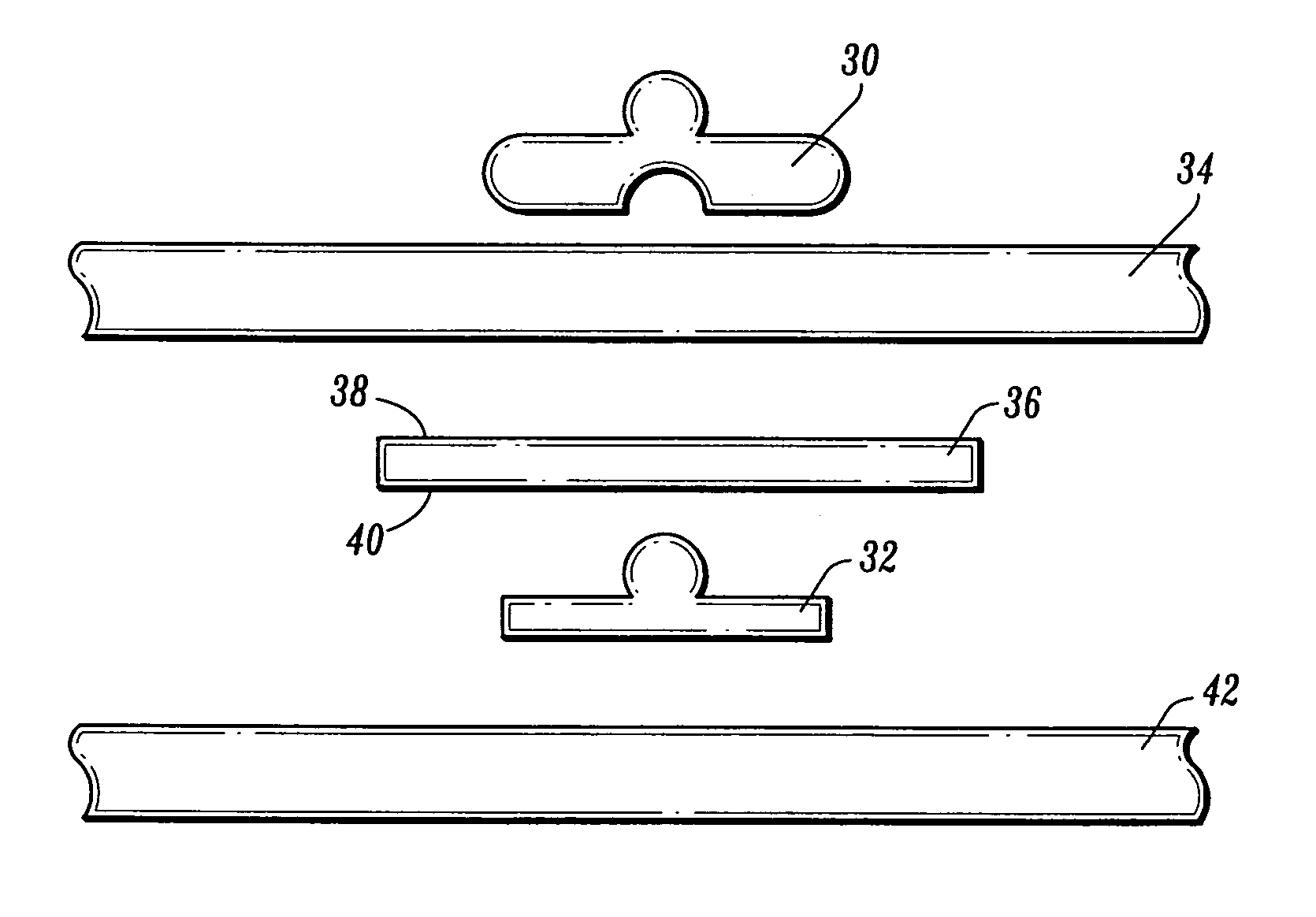
The present invention provides a medical snap electrode with a conductive tape portion that is positioned between the cover layer and the conductive layer and is in electrical contact with the conductive layer. The conductive tape has conductive adhesive on its surface for better electrical connection. The electrode also includes a bottom snap and a top snap for more robust electrical connection. The conductive tape can be pressed between the snap and the conductive layer to provide a more robust electrical connection. The electrode is designed to be more comfortable and less likely to cause skin irritation to the patient. The invention also provides a method for constructing the snap electrode.

Problems solved by technology

In some cases, applications of electrical energy to a subject for EMS and / or measurement of electrical signals causes some apprehension due to the subject's perception that the electrode can burn or otherwise cause discomfort to the subject.
Even though any substantial heating of the electrode or snaps is highly unlikely, it can be envisioned that a defective conductive layer could potentially cause a hot spot touching the patient's of the skin.
Accordingly, many patients and / or practitioners avoid use of appropriate medical electrodes.

Method used


Image

  • Snap electrode
  • Snap electrode
  • Snap electrode

Examples


Embodiment Construction

[0033]The exemplary embodiments of the apparatus and method disclosed herein are discussed in terms of medical snap type electrodes, and more particularly in terms of medical snap electrodes for delivering electrical stimulation to muscle tissue or nerves. It is contemplated that the medical snap type electrode and method disclosed herein may also be used in any manner for which a medical electrode is used including, defibrillation, electrocardiography, electroencephalography and the like.

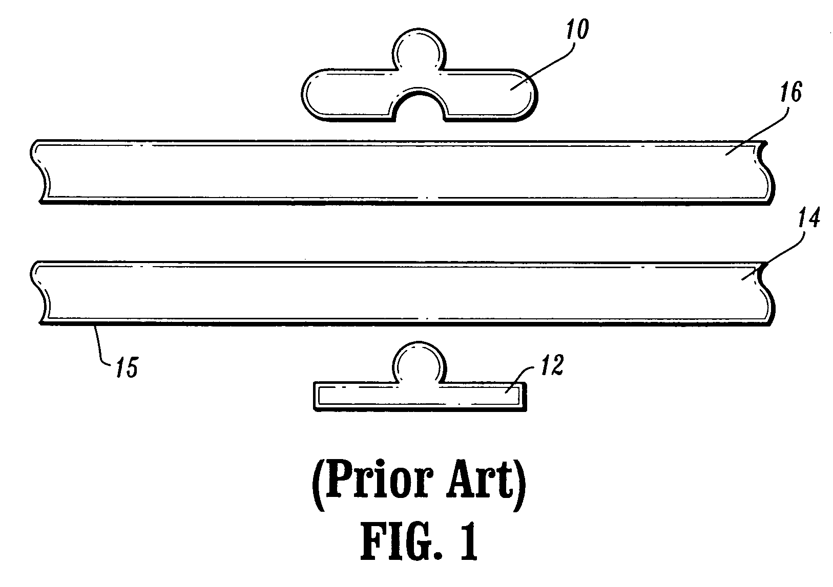
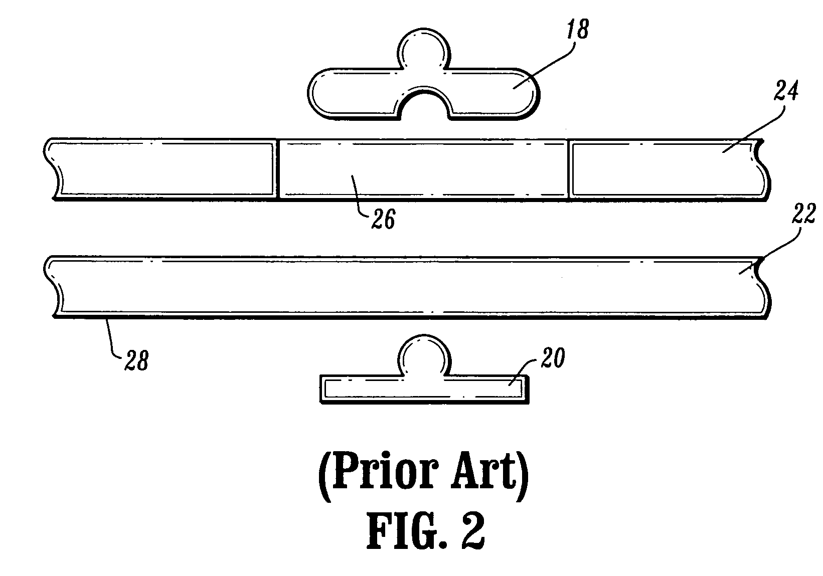
[0034]The following discussion includes a description of the medical snap electrode in accordance with the present disclosure. Reference will be made in detail to exemplary embodiments of the disclosure, which are illustrated in the accompanying figures.

[0035]Turning now to the figures wherein like components are designated by like reference numerals throughout the several views, an illustrative embodiment of the snap type medical electrode according to the present invention is described first with...


PUM


Abstract

A medical snap electrode having a conductive tape portion disposed between the cover material and conduction layer of the electrode. The conductive tape portion becomes part of an electrical connection from a top snap, positioned above the cover material, to the conductive tape then to the conductive layer. The conductive tape includes conductive adhesive on at least one of its surfaces and thereby provides a more robust electrical connection from a top snap to a conductive layer in the electrode and ultimately to a subject's skin. Viewing of the snap through the conductive film layer is prevented. The conductive tape thus provides an improved conduction path for distributing electrical current from the top snap to a subject's skin in addition to the conduction path through bottom snap. The improved conduction path can prevent heating or apprehension of potential heating by a subject or clinician.

Description

[0001]This Application claims the benefit of U.S. Provisional Patent Application No. 60 / 519,322 filed on Nov. 12, 2003, which is hereby incorporated by reference in its entirety.BACKGROUND OF THE INVENTION[0002]1. Technical Field[0003]The present disclosure relates to a biomedical snap electrode and method of manufacturing a biomedical snap electrode for delivering electrical current to a subject. More particularly, a biomedical snap electrode and method of manufacturing a biomedical snap electrode for electrical stimulation of muscle tissue or nerves is disclosed.[0004]2. Description of the Related Art[0005]Medical snap electrodes are well known in the medical field for use in measuring and monitoring the condition of a subject by interpreting various types of electrical signals monitored through the skin of the subject. Some well known applications which use medical snap electrodes include electrocardiography and electroencephalography. In those applications small signals are rece...

Claims


Application Information

Patent Timeline
Patent Type & Authority Patents(United States)
IPC IPC(8): A61B5/04A61B5/274A61N1/04
CPCA61B5/0408A61B5/0416A61B5/0478A61N1/0452A61N1/0456A61N1/0492A61N1/046A61N1/048A61B5/274A61B5/25A61B5/291A61B5/257A61B5/266
Inventor ROWE, CHUCKKRETSCHMER, TIMOTHY R.
Owner KPR U S LLC
Learn More