Construction machine with a quick coupler

a construction machine and coupler technology, applied in mechanical machines/dredgers, lifting devices, applications, etc., can solve the problems of inability to secure operation, write/read head could not exchange data with data carrier, and so on, and achieve the effect of allowing compaction measuremen

Active Publication Date: 2007-07-24
LEIBHERR HYDRAULIKBAGGER GMBH
View PDF20 Cites 19 Cited by
  • Summary
  • Abstract
  • Description
  • Claims
  • Application Information

AI Technical Summary

Benefits of technology

[0006]It is the object of the invention to further develop a generic construction machine with a quick coupling such that technical or technical safety risks on the automatic coupling of the tool to a construction machine are reliably prevented.
[0016]A cleaning system present for the coupling system can also be used simultaneously as a cleaning system for the write / read head and the data carrier. This is in particular advantageous on the use of construction machinery in which particularly the surfaces of the plate-like supports can become dirty.
[0020]The identification of the tool also permits the excavator to be protected in that it can, for example, be avoided here that a tool with the wrong hydraulic oil can be coupled. It is advantageously possible, in addition to the possibility of recognizing the shape and position of a coupled tool (for example, display on a screen) and to the possibility of calculating the stability of the construction machine, to limit the forces acting on the tool for the protection of the tool or of the excavator. For example, a shovel which has dimensions which are too weak can thus be protected from destruction. It is, however, also possible for the tool to advise a maximum load which may not be exceeded an the basis of a forced limitation to be provided in this manner. This can result, for example, in a uniform, optimum compaction with, for example, an added vibrating plate, an added roller compactor or the like. On the other hand, it can also permit a compaction measurement. The controlled observation of a maximum force can make the use of a corresponding construction machine for the transfer of materials, for example an excavator, safer. The base of a hull can, for example, thus be protected by a force limitation of an excavator grab.

Problems solved by technology

This is, however, only the case when the latching bolt engages correctly and connects the system and closes the coupling.
If the bolt would accidentally not close, the spacing would be so large that the write / read head could actually not exchange any data with the data carrier.
If, for example, a radio system with a large transmission path were used here, secure operation would not necessarily be possible since the proneness to problems increases proportionally as the transmission path increases.

Method used


Image

  • Construction machine with a quick coupler
  • Construction machine with a quick coupler
  • Construction machine with a quick coupler

Examples


Embodiment Construction

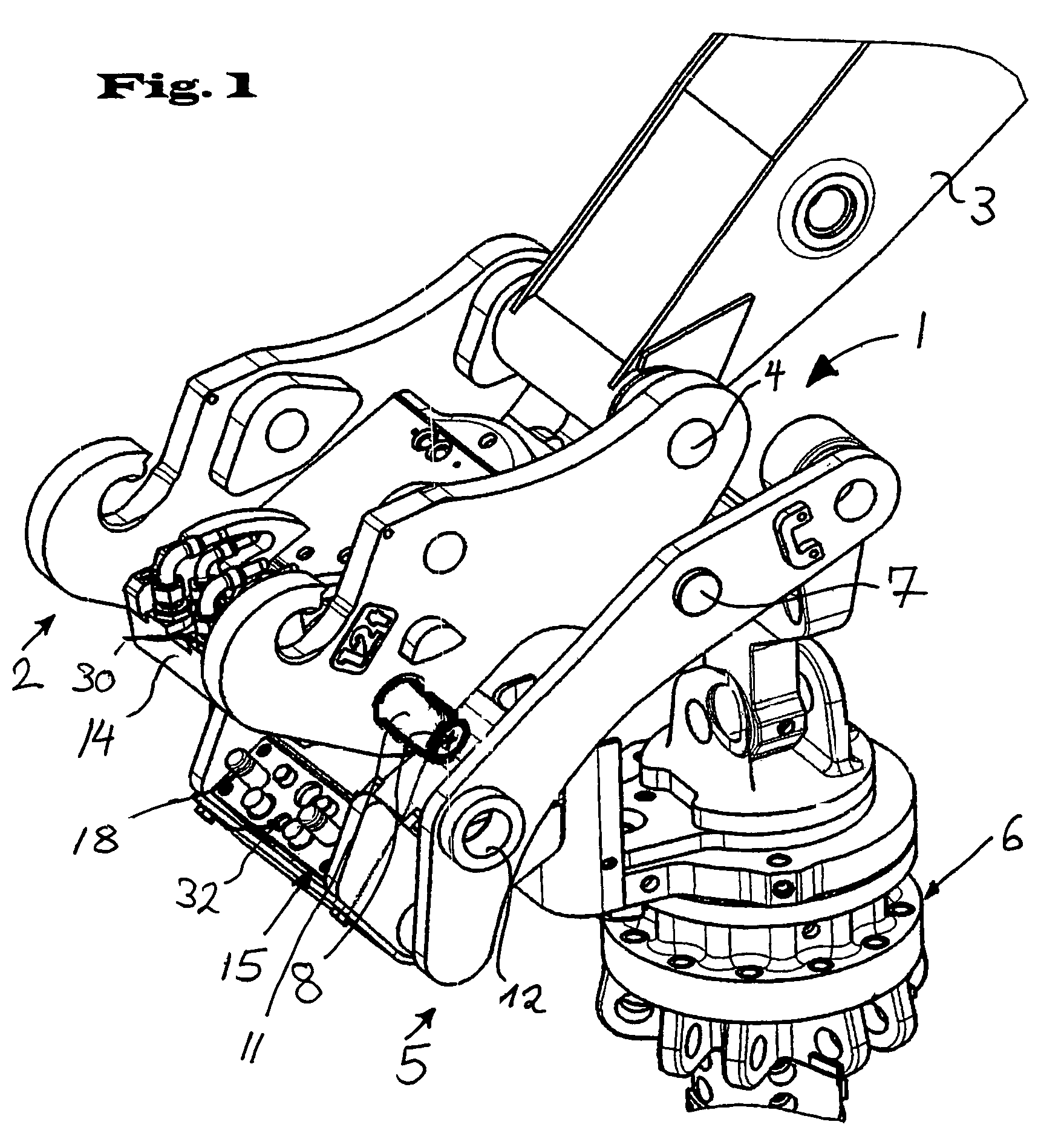
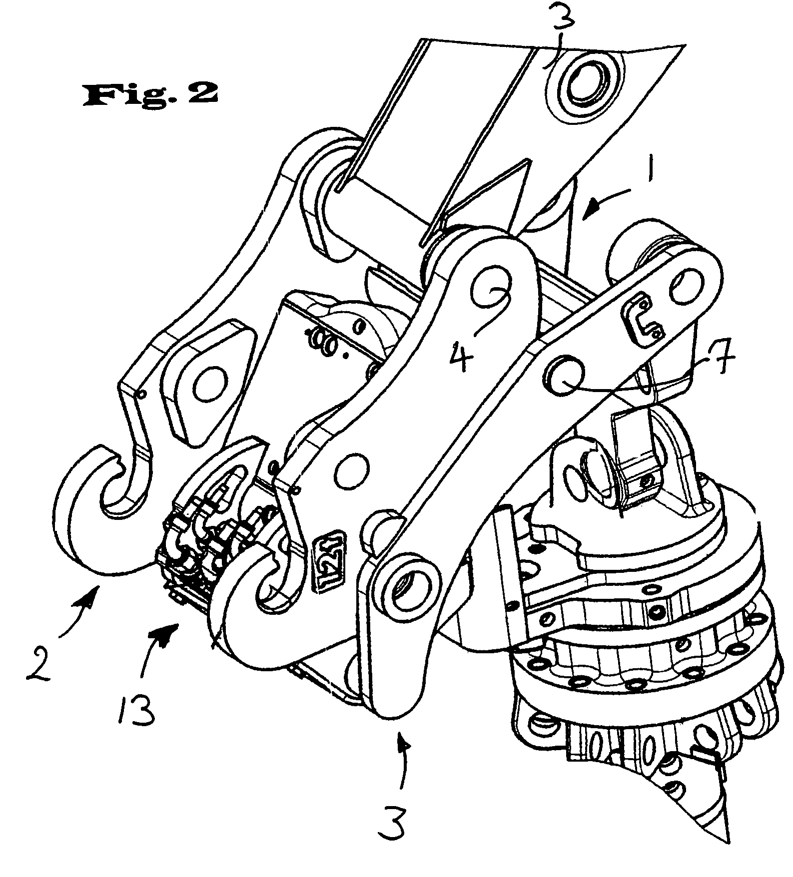
[0030]The quick coupler 1 shown in the Figures has a quick coupling part 2 on the boom side which is pivotably secured to the shaft 3 of a boom of a hydraulic excavator and can be pivoted about the pivot axis 4 perpendicular to the longitudinal axis of the shaft 3 in a manner known per se via a pivot tab not shown in any more detail. The quick coupler 1 furthermore has a quick coupling part 5 on the tool side which is connected to a hydraulic excavator tool. It can e.g. be a grab tool with a rotary mechanism 6 which is hydraulically actuable.

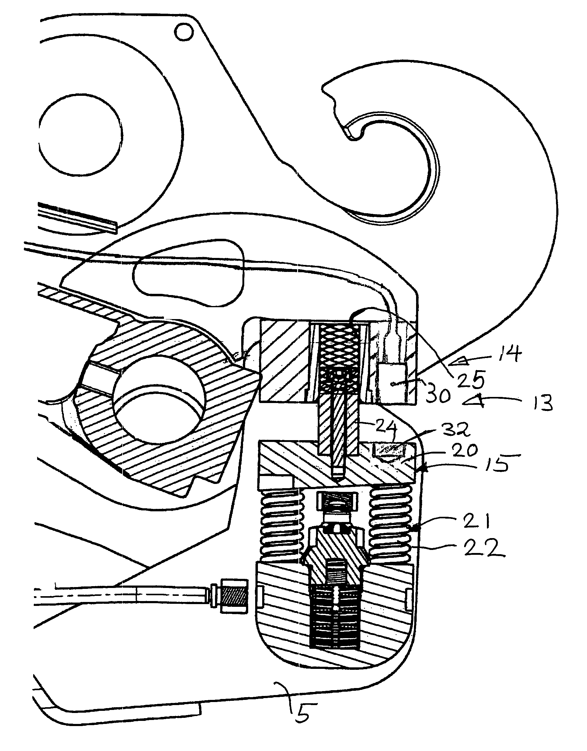
[0031]The two parts 2 and 5 of the quick coupler 1 are latchable to one another via two parallel latching axles 7 and 8 spaced apart from one another. The latching axles 7 and 8 extend, as shown in FIG. 1, parallel to the pivot axis 4 around which the quick coupler 1 can be pivoted relative to the shaft 3. In FIG. 1, the latching bolt 8 is shown in the moved out representation. It can be moved in and out hydraulically.

[0032]The first of the two ...


PUM


Abstract

The invention relates to a construction machine with a quick coupler for the coupling of a tool to a boom having a quick coupling part on the boom side and a quick coupling part on the tool side having a power circuit coupling, in particular a hydraulic coupling, having plate-like supports of the power coupling parts for the automatic coupling of a power connection on the tool side to a power connection on the boom side. In accordance with the invention, a write / read head is arranged in or at one of the two plate-like supports. Furthermore, a data carrier is arranged in the oppositely disposed plate-like support such that both can exchange data with one another in the coupled state.

Description

BACKGROUND OF THE INVENTION [0001]The present invention relates to a quick coupler for the coupling of a tool to a boom having a quick coupling part on the boom side and a quick coupling part on the tool side having a circuit coupling, including a hydraulic coupling, having plate-like supports for the power coupling parts for the automatic coupling of a power connection at the tool side to a power connection at the boom side, with male or female connector pieces being integrated in the plate-like supports, on the one hand, as power connections and with at least one guide bolt or at least one guide bore being integrated spaced apart therefrom in the plate-like supports, which ensure an exactly fitting lying of the plate-like supports on top of one another in the coupled state such that the plate-like supports are arranged largely parallel to one another while forming a small gap.[0002]Quick couplers of the pivot type are widespread in hydraulic excavators, since they permit a simple ...

Claims


Application Information

Patent Timeline
Patent Type & Authority Patents(United States)
IPC IPC(8): E02F3/96E02F3/36E02F9/22E02F9/26
CPCE02F3/3654E02F3/3663
Inventor MIEGER, ROLFZITTERBART, THOMAS
Owner LEIBHERR HYDRAULIKBAGGER GMBH
Why Eureka
Try Eureka