Image forming device

a technology of forming device and forming sheet, which is applied in the direction of typewriters, printing, instruments, etc., can solve the problems of unstable sheet support and reduced surface area of paper supporting section for supporting recording sheets

Active Publication Date: 2007-07-24
BROTHER KOGYO KK
View PDF22 Cites 24 Cited by
  • Summary
  • Abstract
  • Description
  • Claims
  • Application Information

AI Technical Summary

Benefits of technology

[0006]To overcome these problems, it is conceivable to configure the image-forming device with a cover that spans not only the front surface of a casing, but also a paper supporting section provided on the top surface of the casing. When the cover is opened, both the front surface of the casing and a forward region of the paper supporting section open simultaneously, exposing a grip of a process cartridge disposed in an upper front region of the casing. However, while a wide opening can be formed in the device with this construction, facilitating access to the process cartridge, the surface area of the paper supporting section for supporting recording sheets is reduced, and sheet support is unstable.
[0007]In view of foregoing, it is an object of the present invention to overcome the above problems, and also to provide an image-forming device having a casing formed with an opening, through which detachable parts may be inserted or removed, in its front and top surfaces, facilitating access to the inside of the casing, but top surface portions of the casing can support recording sheets with stability.

Problems solved by technology

However, while a wide opening can be formed in the device with this construction, facilitating access to the process cartridge, the surface area of the paper supporting section for supporting recording sheets is reduced, and sheet support is unstable.

Method used


Image

  • Image forming device
  • Image forming device
  • Image forming device

Examples


first embodiment

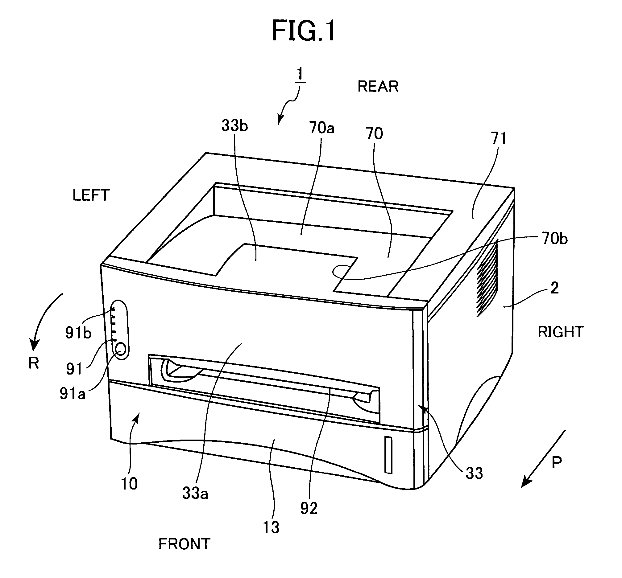
[0028]Next, the present invention will be described with reference to FIGS. 1 to 7 in which the image-forming device according to the present invention is applied to a laser beam printer.

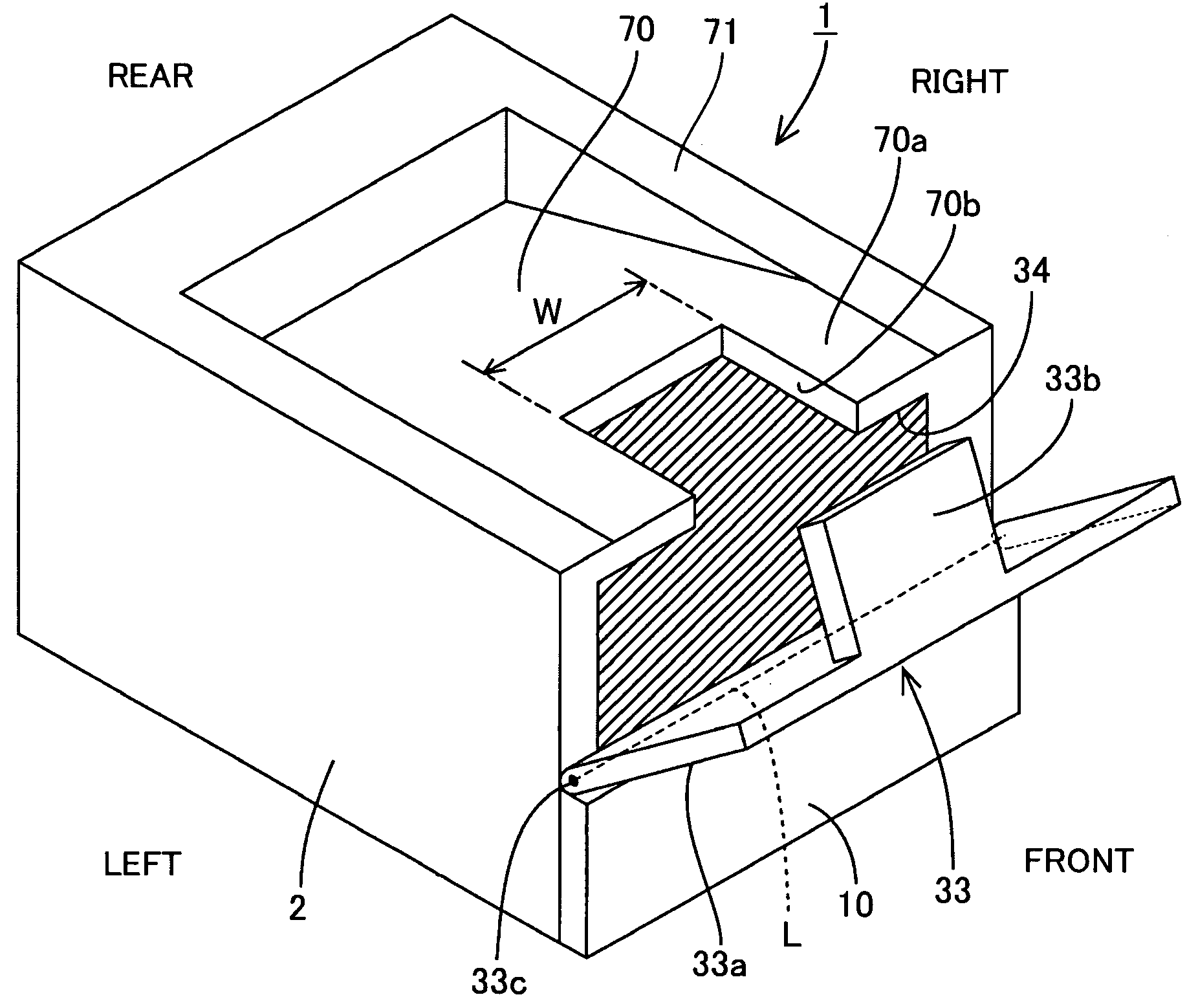
[0029]As shown in FIG. 1, a laser beam printer 1 according to the first embodiment includes a main casing 2 having a substantially rectangular parallelepiped shape. A sheet supply cassette 10 for supporting a stack of recording sheets S (FIG. 6) is disposed in the lower section of the main casing 2. The sheet supply cassette 10 is formed with a grip 13 and can be detached from the main casing 2 by being pulled toward the front as indicated by an arrow P.

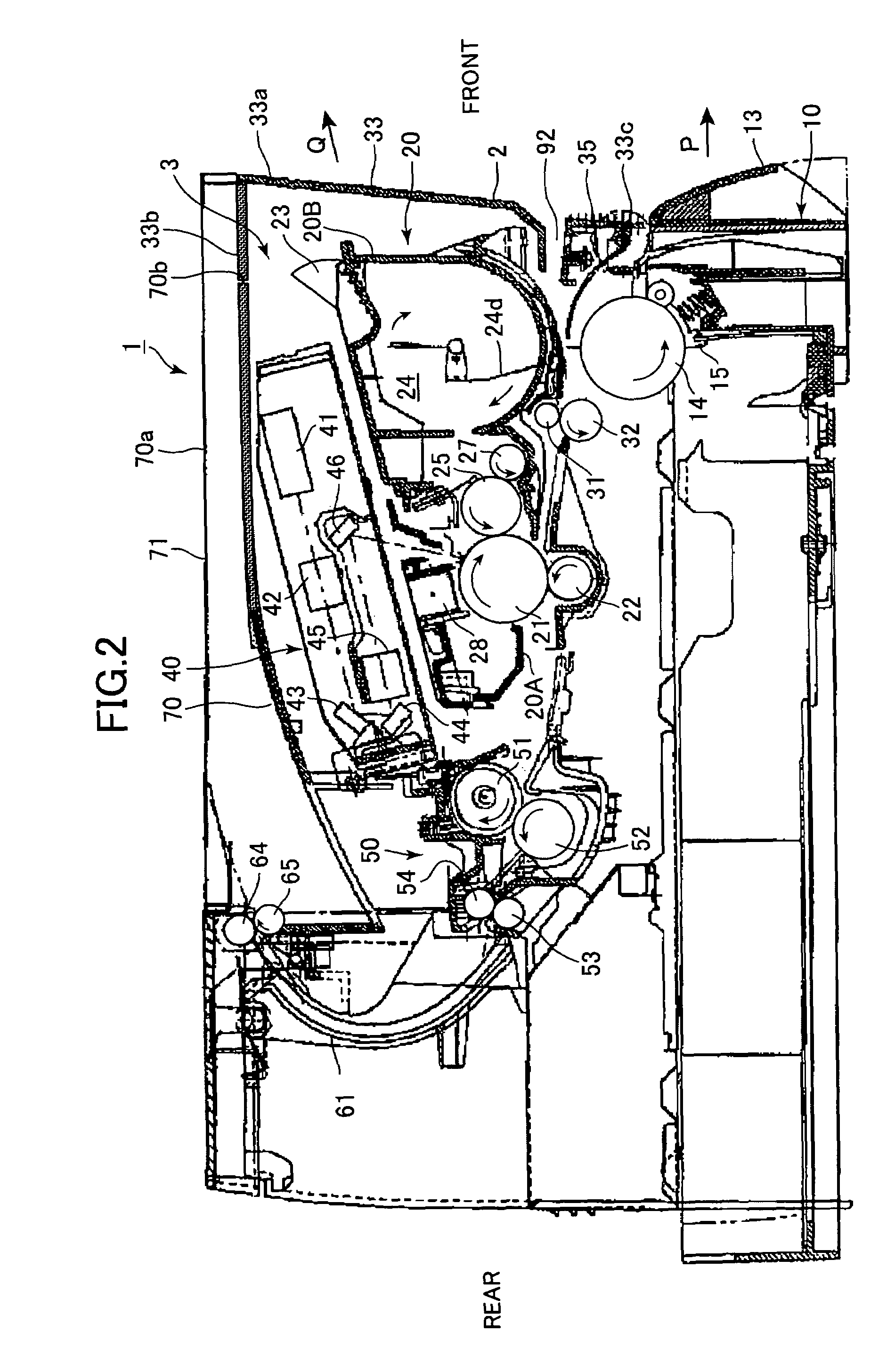
[0030]Although not shown in the drawings, the sheet supply cassette 10 includes a pressing plate for mounting a stack of recording sheets S and a spring for urging the pressing plate upward. As shown in FIG. 2, a sheet supply roller 14 is disposed inside the main casing 2 so as to be rotatable in a direction indicated by an arrow. An uppermost sheet ...

third embodiment

[0060]Next, a laser beam printer 200 according to the present invention will be described with reference to FIGS. 10 and 11. Note that components similar to that of the above-described embodiments will the assigned with the same numberings, and description thereof will be omitted to avoid duplication in explanation.

[0061]As shown in FIG. 11, the laser beam printer 200 has a cover 233 disposed on the front surface of the main casing 2 that differs from the cover 33 according to the first embodiment. The cover 233 includes a front cover part 233a and a top cover part 233b configured to pivot about an axis C2 on the front cover part 233a. A step part 33e is formed in the top cover part 233b. An angle formed by the front cover part 233a and the top cover part 233b is maintained slightly smaller than 90° (such as 80°) by a spring member 33d.

[0062]The laser beam printer 200 also has a discharge tray 270. As shown in FIG. 10, the discharge tray 270 includes a tapered part 276 formed on th...

fourth embodiment

[0064]Next, a laser beam printer 300 according to the present invention will be described with reference to FIG. 12. Description of components similar to that of the above-described embodiments will be omitted to avoid duplication in explanation.

[0065]The laser beam printer 300 shown in FIG. 12 includes a main casing 302 and a sheet supply cassette 310 that is inserted into the front side of the main casing 302. The main casing 302 is formed with an opening 334 continuous with the cutout part 70b. The sheet supply cassette 310 includes a front wall 311 that constitutes the entire front surface of the main casing 302 and extends to the top surface of the main casing 302. The front wall 311 includes a front cover part 311a and a plate-shaped top cover part 311b that are integrally formed and function as a cover for the opening 334 and the cutout part 70b. The front wall 311 moves forward and rearward during operations to open and close the sheet supply cassette 310, thereby exposing a...


PUM


Abstract

A laser beam printer includes a casing with a discharge tray disposed on the top surface of the casing. A cutout part is formed in the top surface of the casing and an opening is formed in the front surface of the casing for facilitating mounting and removal of a process cartridge. The opening can be closed with a cover. When the cover is in a closed position, a top cover part of the cover blocks the cutout part. At this time, the top cover part and a main discharge tray part of the discharge tray are adjacent to one another and function to support paper. When the cover is in an open position, the cutout part is exposed; the top cover part is separated from the main discharge tray part; and the paper is supported by the main discharge tray alone.

Description

BACKGROUND OF THE INVENTION[0001]1. Field of the Invention[0002]The present invention relates to an image forming device.[0003]2. Related Art[0004]Image-forming devices well known in the art include a front access type printer. This type of printer has a casing formed with an opening in its front surface, and a cover capable of swinging open and closed on the casing to expose or cover the opening. Hence, process cartridges and other detachable parts can be installed to or removed from the casing through the opening by opening this cover. Because of its user-friendliness, this construction has been made employed in various practical devices, such as that disclosed in Japanese unexamined patent application publication No. 2002-111243.[0005]To meet today's demands, however, devices must not only be user-friendly, but also thin and compact. In order to satisfy these needs, restrictions have been placed on the layout of these devices. Accordingly, when conventional configurations are use...

Claims


Application Information

Patent Timeline
Patent Type & Authority Patents(United States)
IPC IPC(8): B41J29/02B41J29/13B41J29/00B41J13/10G03G21/16
CPCB41J13/106
Inventor NISHIMURA, SOICHIRO
Owner BROTHER KOGYO KK
Why Eureka
Try Eureka