Limited slip differential device
a differential device and limited technology, applied in the direction of magnets, magnetic bodies, gearings, etc., can solve the problem that the differential device keeps the slip-limit state, and achieve the effect of limiting the differential function of the differential gear
- Summary
- Abstract
- Description
- Claims
- Application Information
AI Technical Summary
Benefits of technology
Problems solved by technology
Method used
Image
Examples
first embodiment
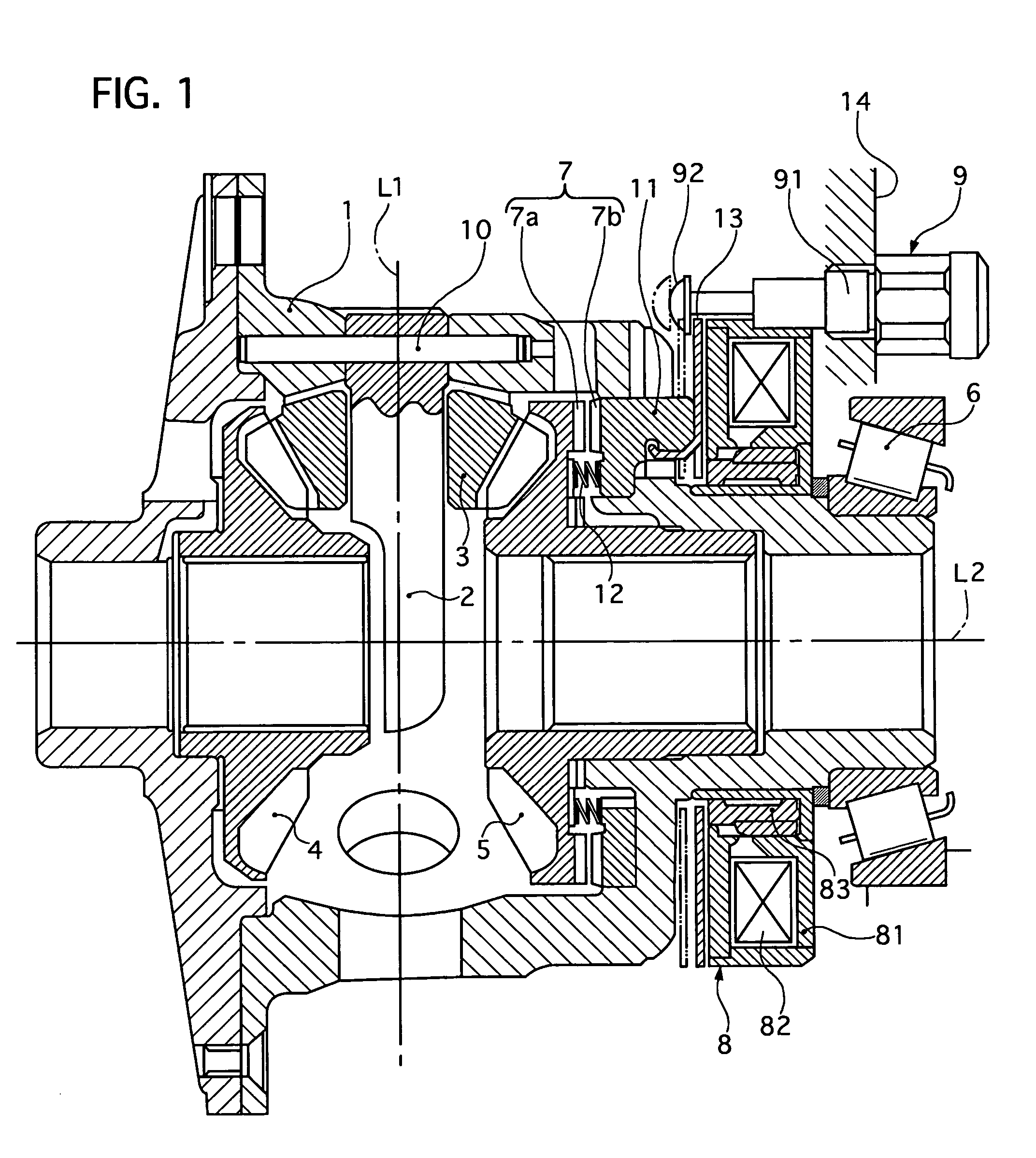
[0031]FIGS. 3A and 3B show a differential limit mechanism in a differential unlock state and in a differential lock state, respectively, when the differential limit mechanism is constructed to have a plunger without a cut-off portion, for the sake of comparison with the differential limit mechanism 8 with the cut-off portions of the
[0032]The differential limit mechanism 8′ includes a yoke 81′, a coil 82′ disposed inside the yoke 81′, and a plunger 831′. The plunger 831′ has an outer ring part 831′ and an inner ring part 832′ as well as those of the first embodiment, except that they are not cut-off at their front and rear ends. In the differential unlock state, the coil 82′ is de-energized, and the plunger 83′ is pressed back by a return spring, not shown, to contact with a rear inner wall portion 81c′ of the yoke 82′ and disengage a dog clutch as shown in FIG. 3A. In the differential lock state, the coil 82′ is energized, and the plunger moves forward to push a piton plate, not sho...
second embodiment
[0045]Next, a limited differential device of a second embodiment will be described with reference to the accompanying drawing of FIG. 4.
[0046]This differential device has a structure equipped with differential gears, a dog clutch, and a linear electromagnetic solenoid, which are similar to that of the first embodiment except configurations of a plunger and a yoke of a linear electromagnetic solenoid.
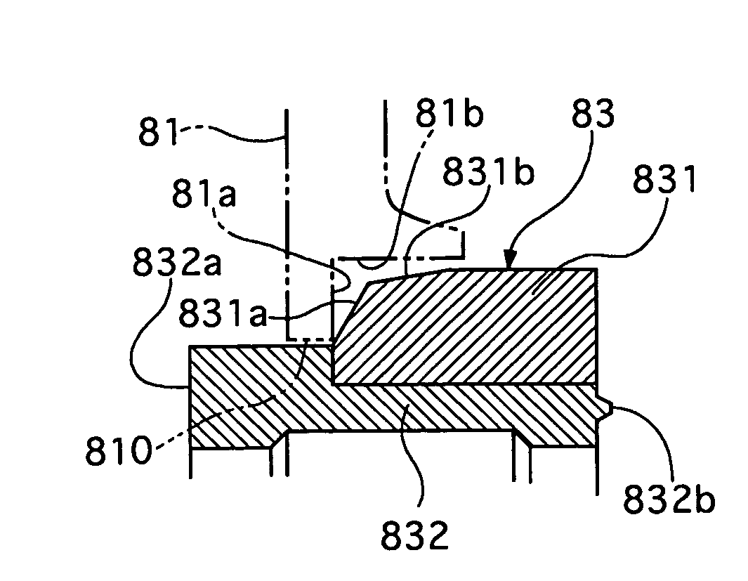
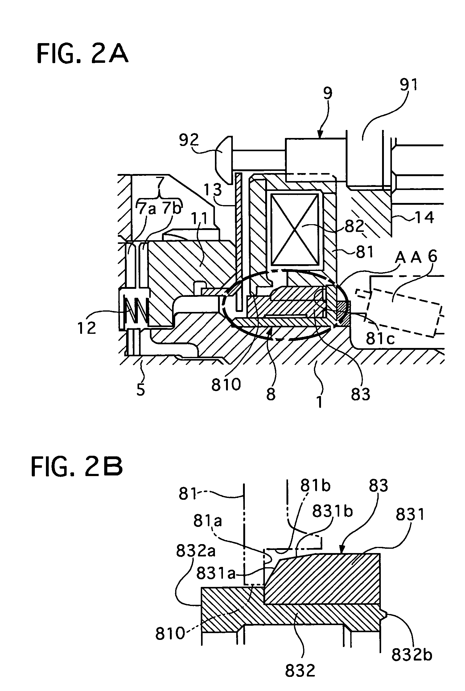
[0047]As shown in FIG. 4, a plunger 83 includes an outer ring part 831 and an inner ring part 832, which are joined with each other by press fit or the like. The outer ring part 831 has not a first and outer tapered portion such as those of the first embodiment, while a yoke 81 is formed at its center portion with a hole 810 surrounded by an inner stepped portion having an inner tapered surface 81d, an inner radial surface 81a, and an inner cylindrical surface 81b by cutting off an inner portion of the yoke 81. The inner tapered surface 81d is kept away from the outer ring part 831 when ...
third embodiment
[0052]Next, a limited differential device of a third embodiment will be described with reference to the accompanying drawing of FIG. 5.
[0053]This differential device has a structure equipped with differential gears, a dog clutch, and a linear electromagnetic solenoid, which are similar to that of the first embodiment except configurations of a plunger and a yoke of a linear electromagnetic solenoid.
[0054]As shown in FIG. 5, a plunger 83 includes an outer ring part 831 and an inner ring part 832, which are joined with each other by press fit or the like. The outer ring part 831 has not a first and outer tapered portion such as those of the first embodiment, while a yoke 81 is formed at its center portion with a hole 810 surrounded by an inner stepped portion having an inner circular projecting portion 81e, an inner radial surface 81a, and an inner cylindrical surface 81b by cutting off an inner portion of the yoke 81. The inner circular projecting portion 81e contacts with an outer r...
PUM
| Property | Measurement | Unit |
|---|---|---|
| electromagnetic force | aaaaa | aaaaa |
| area | aaaaa | aaaaa |
| spring force | aaaaa | aaaaa |
Abstract
Description
Claims
Application Information
 - R&D
- Intellectual Property
- Life Sciences
- Materials
- Tech Scout
- Unparalleled Data Quality
- Higher Quality Content
- 60% Fewer Hallucinations
Browse by: Latest US Patents, China's latest patents, Technical Efficacy Thesaurus, Application Domain, Technology Topic, Popular Technical Reports.
© 2025 PatSnap. All rights reserved.Legal|Privacy policy|Modern Slavery Act Transparency Statement|Sitemap|About US| Contact US: help@patsnap.com


