Orthogonal weaving for complex shape preforms

a technology of complex shapes and weaving, applied in the field of composite preforms, to achieve the effect of increasing the performance of aircraft gas turbine engines, reducing costs, and increasing performan

Active Publication Date: 2007-07-24
GENERAL ELECTRIC CO
View PDF28 Cites 27 Cited by
  • Summary
  • Abstract
  • Description
  • Claims
  • Application Information

AI Technical Summary

Benefits of technology

[0009]Improvements in manufacturing technology and materials are the keys to increased performance and reduced costs for many articles. As an example, continuing and often interrelated improvements in processes and materials have resulted in major increases in the performance of aircraft gas turbine engines, such as the improvements of the present invention. The present invention is a novel method for manufacturing a turbine engine component made from a ceramic matrix composite (CMC) by weaving a three-dimensional composite preform that provides a tailored fiber architecture that may be assembled near-net-shape. A near-net-shape is a shape for a composite preform that, after weaving, requires little or no trimming prior to final fabrication of the composite. The present invention produces a component tailored to an intricate, complex shape having the advantage of a fine unit cell size inside the weave, wherein the resultant composite has superior mechanical properties and erosion resistance.
[0010]The method of the present invention is particularly suitable for fabrication of turbine airfoil components for gas turbine engines. In particular, the method of the present invention is suitable for the fabrication of stationary turbine vanes for use in gas turbine engines. The method of the present invention is particularly suitable for composites having complex and / or intricate shapes, such as stationary turbine vanes, because the method allows fabrication of preforms of a complex and / or intricate shape that does not require trimming (i.e., near-net-shape) prior to final fabrication into the composite.

Problems solved by technology

One disadvantage of existing methods for production of CMC preforms is that the fibers that provide advantageous structural properties to a composite are not positioned and interlocked or interwoven to provide an optimal fiber architecture.
Conventional methods of three-dimensional composite performing typically involve fabricating woven, or braided shapes that do not provide the desired complex preform shapes.

Method used


Image

  • Orthogonal weaving for complex shape preforms
  • Orthogonal weaving for complex shape preforms
  • Orthogonal weaving for complex shape preforms

Examples


Embodiment Construction

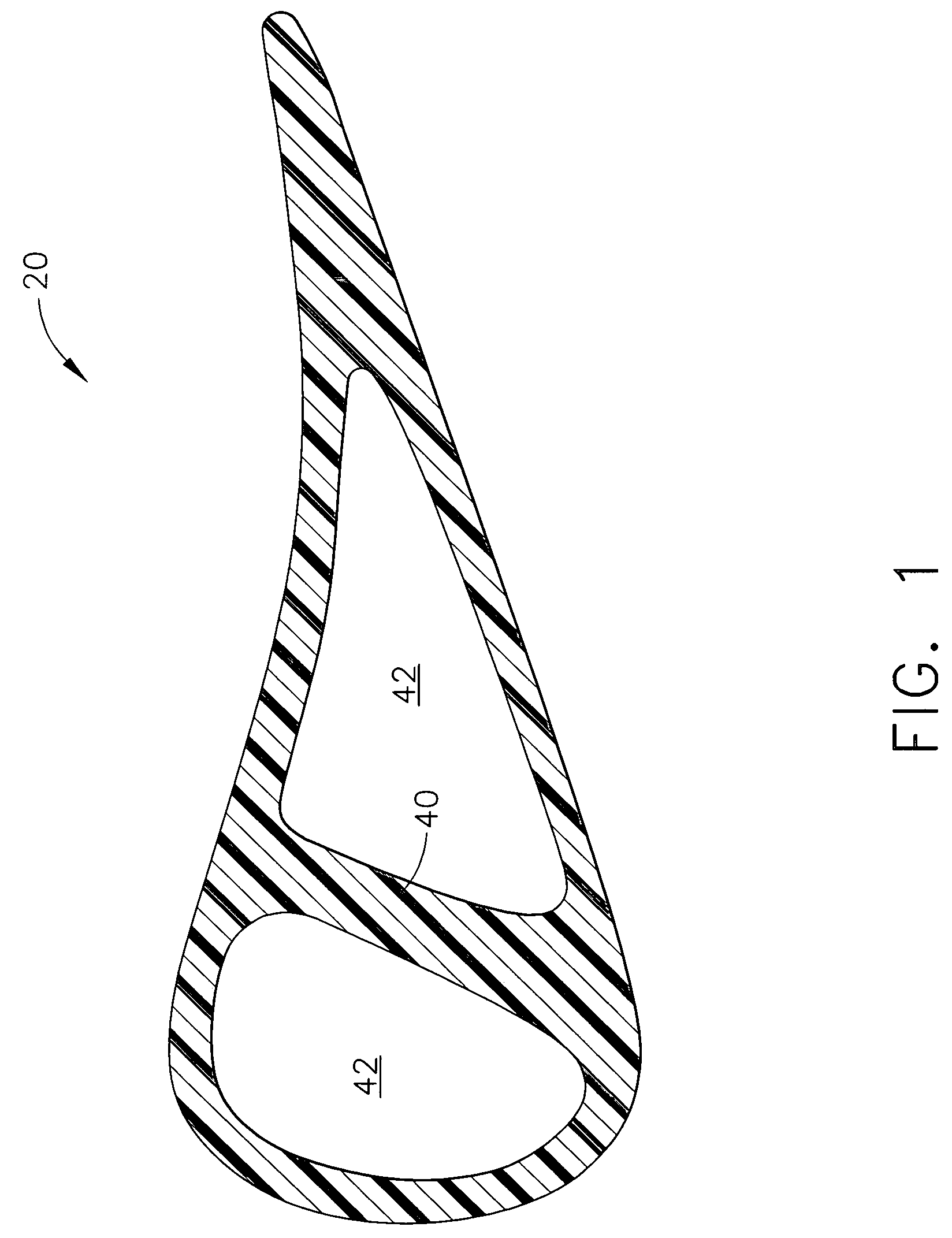
[0023]FIG. 1 illustrates a sectional view of vane 20. Vane 20 is a relatively complex three dimensional shape that includes a structural stiffener 40 and cooling air channels 42. During engine operation, cool, compressed air is bled from a compressor section of a gas turbine engine (not shown) and directed through channels 42 to cool vane 20.

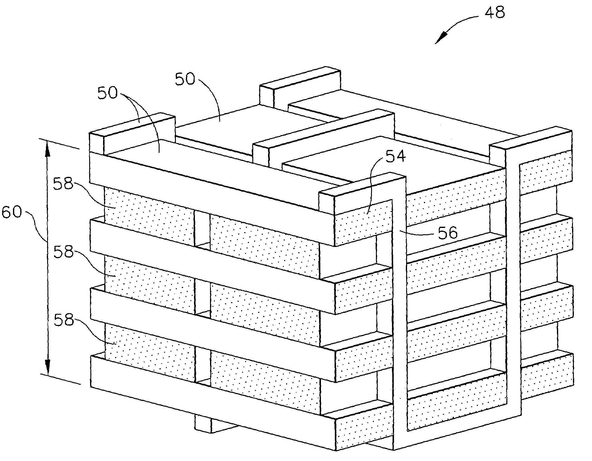
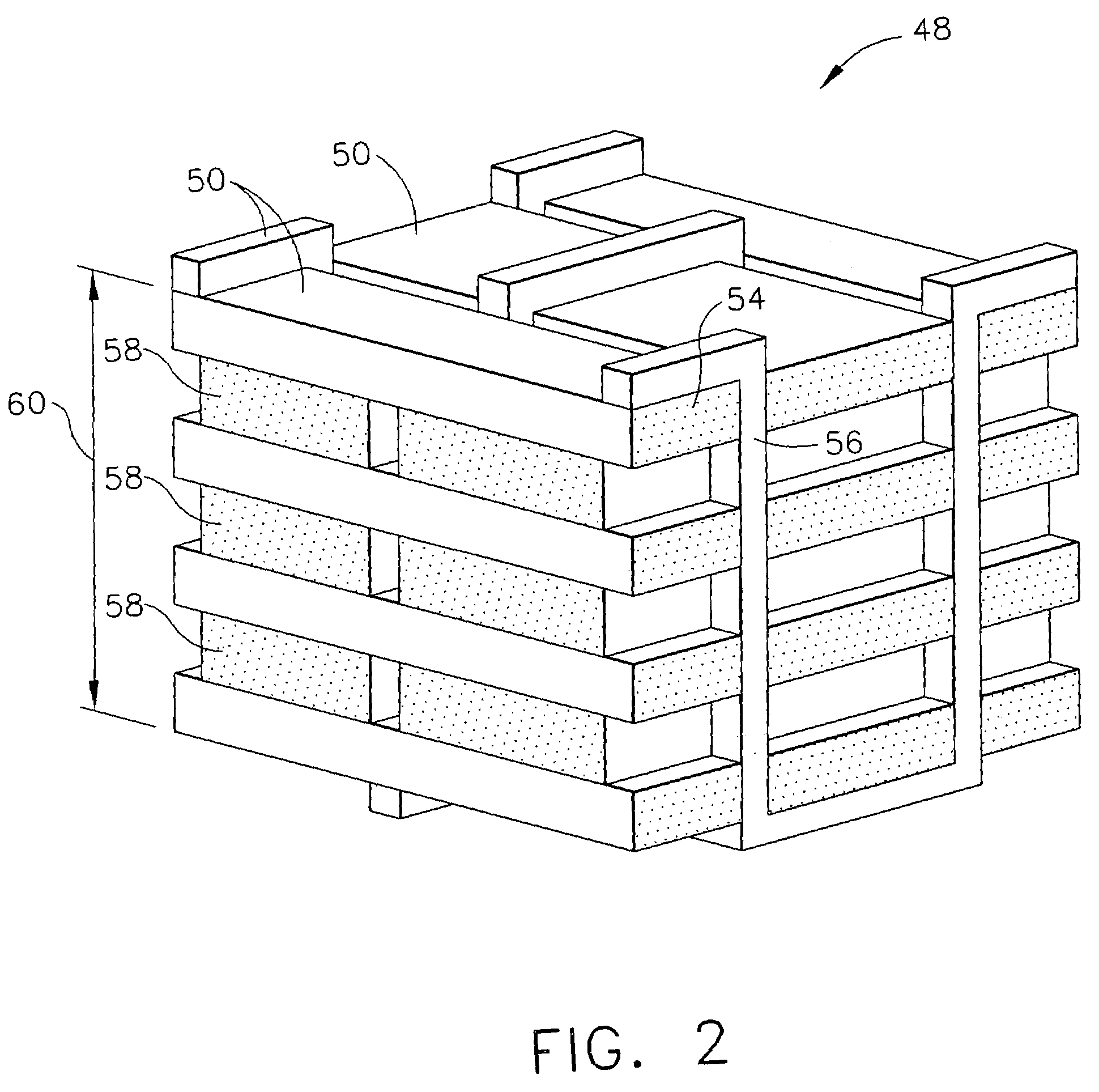
[0024]FIG. 2 is a perspective representation of the stitch-weave 48 of the present invention illustrating a plurality of fiber tows 50 arranged in a preferred architecture. As will be appreciated, FIG. 2 depicts the pattern created by the present invention. Fiber tows 50 are made up of one or a plurality of long, relatively thin smaller fibers. As shown in FIG. 2, fiber tows 50 include three types including: weft tows 54, a stitcher tows 56 and warp tows 58. The smaller fibers making up the fiber tows 50 are any fiber suitable for the construction of preforms for ceramic matrix composites. The fibers may include, but are not limited to silicon c...


PUM

PropertyMeasurementUnit
diametersaaaaaaaaaa
anglesaaaaaaaaaa
lengthaaaaaaaaaa

Abstract

An orthogonal stitch-weave method and fiber architecture. The architecture allows near-net-shape composite preforms to be fabricated, thereby reducing costs associated with complex preform shapes and increasing desired strengths of the composite.

Description

STATEMENT REGARDING FEDERALLY SPONSORED RESEARCH OR DEVELOPMENT[0001]This invention was made with government support under Contract No. F33615-C-2893. The government may have certain rights to the invention.FIELD OF THE INVENTION[0002]The present invention relates generally to composite preforms and methods for making composite preforms.BACKGROUND OF THE INVENTION[0003]In a gas turbine engine, air is pressurized in a compressor and mixed with fuel in a combustor and ignited for generating hot combustion gasses which flow downstream through several turbine stages. A turbine stage includes stationary turbine vanes extending radially between inner and outer castings. The vanes are hollow with openings that mate to openings within the castings. The vanes have airfoil configurations for guiding the combustion gasses between corresponding turbine rotor blades disposed downstream of the vanes. The blades are mounted to the perimeter of a rotor disk that rotates during operation for providi...

Claims


Application Information

Patent Timeline
Patent Type & Authority Patents(United States)
IPC IPC(8): C04B35/80D03D1/00D03D23/00F01D5/28F02C7/00
CPCB28B19/00C04B35/573C04B35/83D03D25/005D03D41/004C04B2235/5224C04B2235/5228C04B2235/5244C04B2235/5256Y10T442/3195B29B11/16
Inventor KOSTAR, TIMOTHY DANIELCARPER, DOUGLAS MELTONSUBRAMANIAN, SURESH
Owner GENERAL ELECTRIC CO
Why Eureka
Try Eureka