Scattered pilot pattern and channel estimation method for MIMO-OFDM systems

a pilot pattern and channel estimation technology, applied in the field of scattered pilot pattern and channel estimation method of mimoofdm system, can solve the problems of only suitable pattern, only challenging minimum overhead, only suitable pattern, etc., and achieve the effect of reducing scattered pilot overhead, less computational complexity, and robustness

Active Publication Date: 2007-07-24
MALIKIE INNOVATIONS LTD
View PDF12 Cites 205 Cited by
  • Summary
  • Abstract
  • Description
  • Claims
  • Application Information

AI Technical Summary

Benefits of technology

[0021]Channel estimation methods are provided which are based on the partial interpolation of a scattered pilot by using true 2-D interpolation; and additionally, simple 1-D interpolation is used reconstruct the entire channels. This method has a reduced scattered pilot overhead, and is at least an order of magnitude less computationally complex than some existing methods. In general, the proposed method of channel estimation is more robust in channels with high Doppler spread, and provides better performance than some existing methods and requires the less buffering of the OFDM symbols for the coherent detection at the receiver than in some methods.
[0022]The methods allow fewer pilot symbols to be placed within each OFDM symbol, while still allowing accurate interpolation of the channel response. The data rate of an MIMO-OFDM system is thereby improved.

Problems solved by technology

To interpolate and reconstruct the channel response function from the limited pilots to achieve reliable channel estimation with the minimum overhead is a challenging task.
However, such a pilot pattern is only suitable for channels that vary very slowly with time.
However, such a pilot pattern is only suitable for channels that vary slowly with frequency.
However, because pilot symbols are overhead, a tighter pilot pattern is at the expense of the transmitted data rate.
This increases the overhead in the signal.
The problem of minimizing the number of pilot symbols while maximizing the accuracy of the interpolation is also particularly cumbersome in Multiple-Input Multiple-Output (MIMO) OFDM systems.
This increases the temporal separation of the pilot symbols for each transmitter, reducing the accuracy of the interpolation used to estimate the channel response.

Method used


Image

  • Scattered pilot pattern and channel estimation method for MIMO-OFDM systems
  • Scattered pilot pattern and channel estimation method for MIMO-OFDM systems
  • Scattered pilot pattern and channel estimation method for MIMO-OFDM systems

Examples


Embodiment Construction

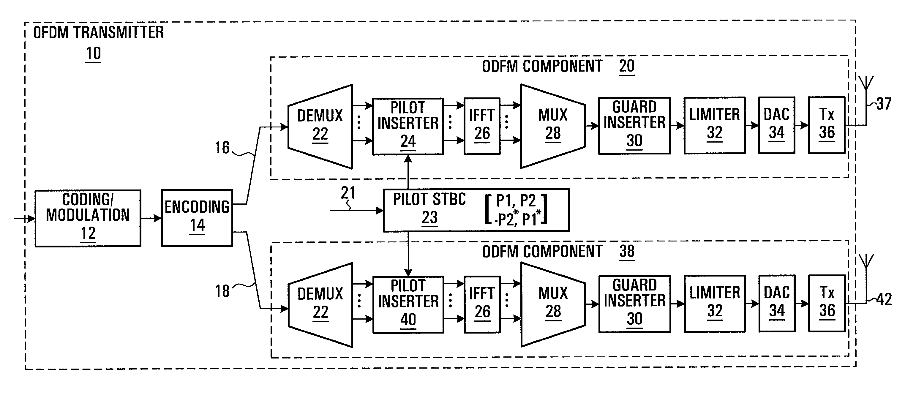
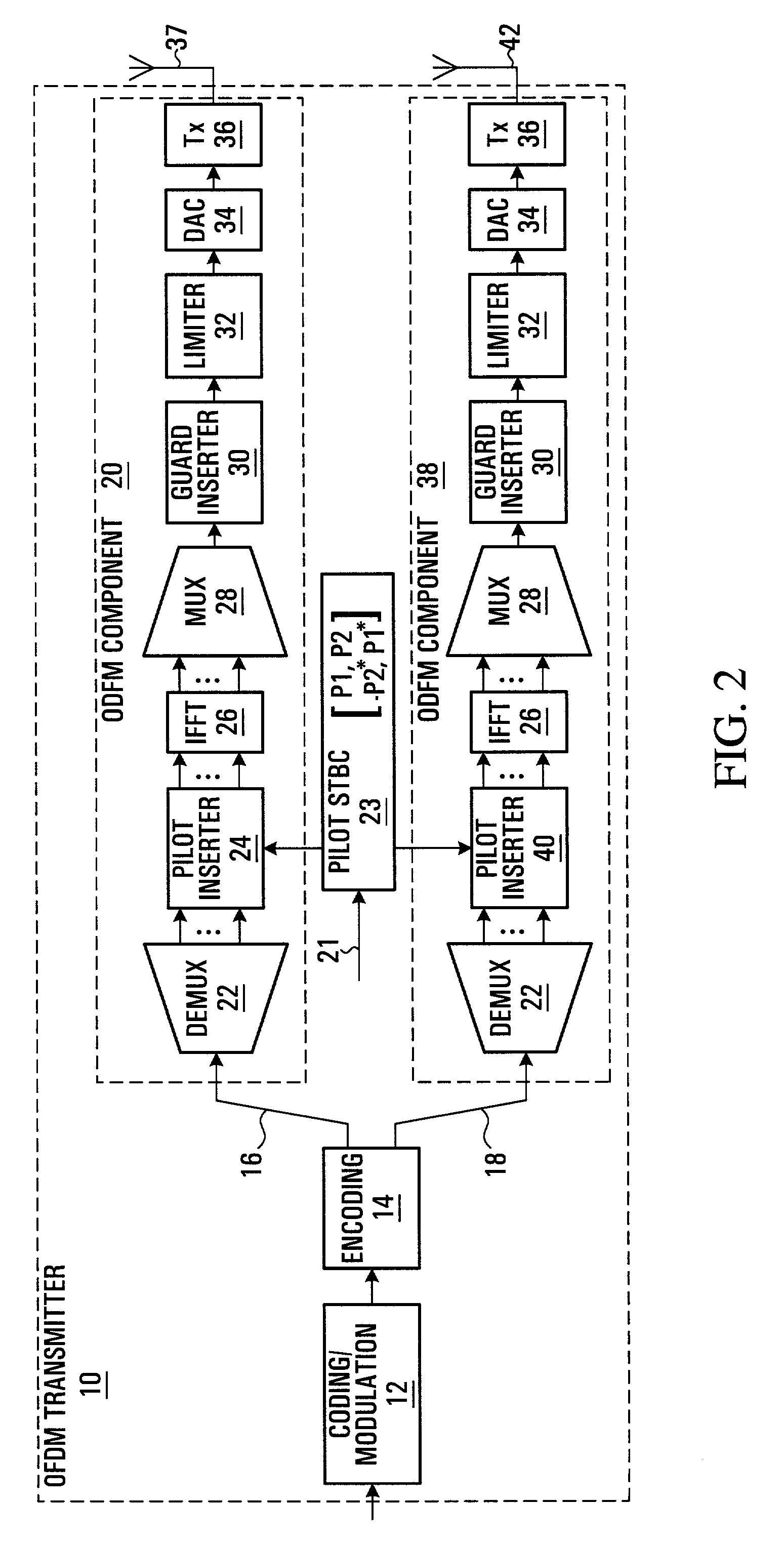
[0060]The following sections describe a MIMO-OFDM transmitter / receiver and scattered pilot insertion. By way of introduction, a OFDM frame consists of the preamble OFDM symbols and regular OFDM symbols. Each OFDM symbol uses a set of orthogonal sub-carriers. When there are two transmit antennas, two OFDM symbols form a STTD block. For regular OFDM symbols, some sub-carriers are used as pilot sub-carriers to carry pilot symbols while the others are used as data sub-carriers to carry data symbols. The pilot sub-carriers are modulated by pilot symbols generated by QPSK. The data sub-carriers are modulated by complex data symbols generated by QAM mapping. STTD coding is applied to the pilot sub-carrier pairs located at the same frequency within one STTD block.

[0061]Referring to FIG. 2, a block diagram of a Multiple-Input Multiple-Output (MIMO) Orthogonal Frequency Division Multiplexing (OFDM) transmitter provided by an embodiment of the invention is shown. The OFDM transmitter shown in ...


PUM


Abstract

A method and apparatus are provided for reducing the number of pilot symbols within a MIMO-OFDM communication system, and for improving channel estimation within such a system. For each transmitting antenna in an OFDM transmitter, pilot symbols are encoded so as to be unique to the transmitting antenna. The encoded pilot symbols are then inserted into an OFDM frame to form a diamond lattice, the diamond lattices for the different transmitting antennae using the same frequencies but being offset from each other by a single symbol in the time domain. At the OFDM receiver, a channel response is estimated for a symbol central to each diamond of the diamond lattice using a two-dimensional interpolation. The estimated channel responses are smoothed in the frequency domain. The channel responses of remaining symbols are then estimated by interpolation in the frequency domain.

Description

RELATED APPLICATION[0001]This application claims the benefit of U.S. provisional application No. 60 / 329,509 filed Oct. 17, 2001.FIELD OF THE INVENTION[0002]This invention relates to OFDM communication systems, and more particularly to a more efficient use of pilot symbols within such systems.BACKGROUND OF THE INVENTION[0003]Multiple Input Multiple Output-Orthogonal Frequency Division Multiplexing (MIMO-OFDM) is a novel highly spectral efficient technology used to transmit high-speed data through radio channels with fast fading both in frequency and in time.[0004]In wireless communication systems that employ OFDM, a transmitter transmits data to a receiver using many sub-carriers in parallel. The frequencies of the sub-carriers are orthogonal. Transmitting the data in parallel allows the symbols containing the data to be of longer duration, which reduces the effects of multi-path fading. The orthogonality of the frequencies allows the sub-carriers to be tightly spaced, while minimizi...

Claims


Application Information

Patent Timeline
Patent Type & Authority Patents(United States)
IPC IPC(8): H04J11/00H04B7/02H04B7/216H04L27/00H04Q7/00H04L1/06H04L5/02H04L25/02H04L27/26
CPCH04B7/04H04B7/0684H04L1/0618H04L5/0023H04L5/0048H04L27/2627H04L25/022H04L25/0234H04L25/0244H04B7/0413H04L27/2602H04L25/0204H04L27/26035H04L27/26134H04L27/2613H04L27/26H04W52/42
Inventor MA, JIANGLEIJIA, MINGZHU, PEIYINGTONG, WEN
Owner MALIKIE INNOVATIONS LTD
Why Eureka
Try Eureka