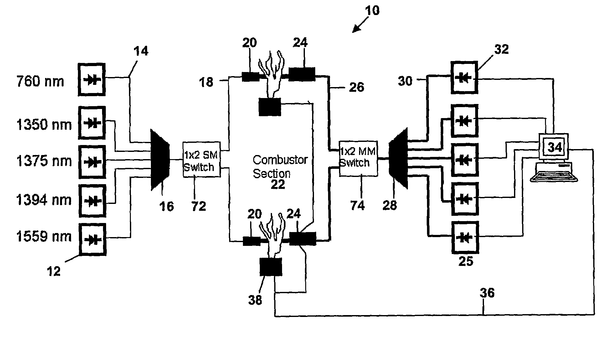
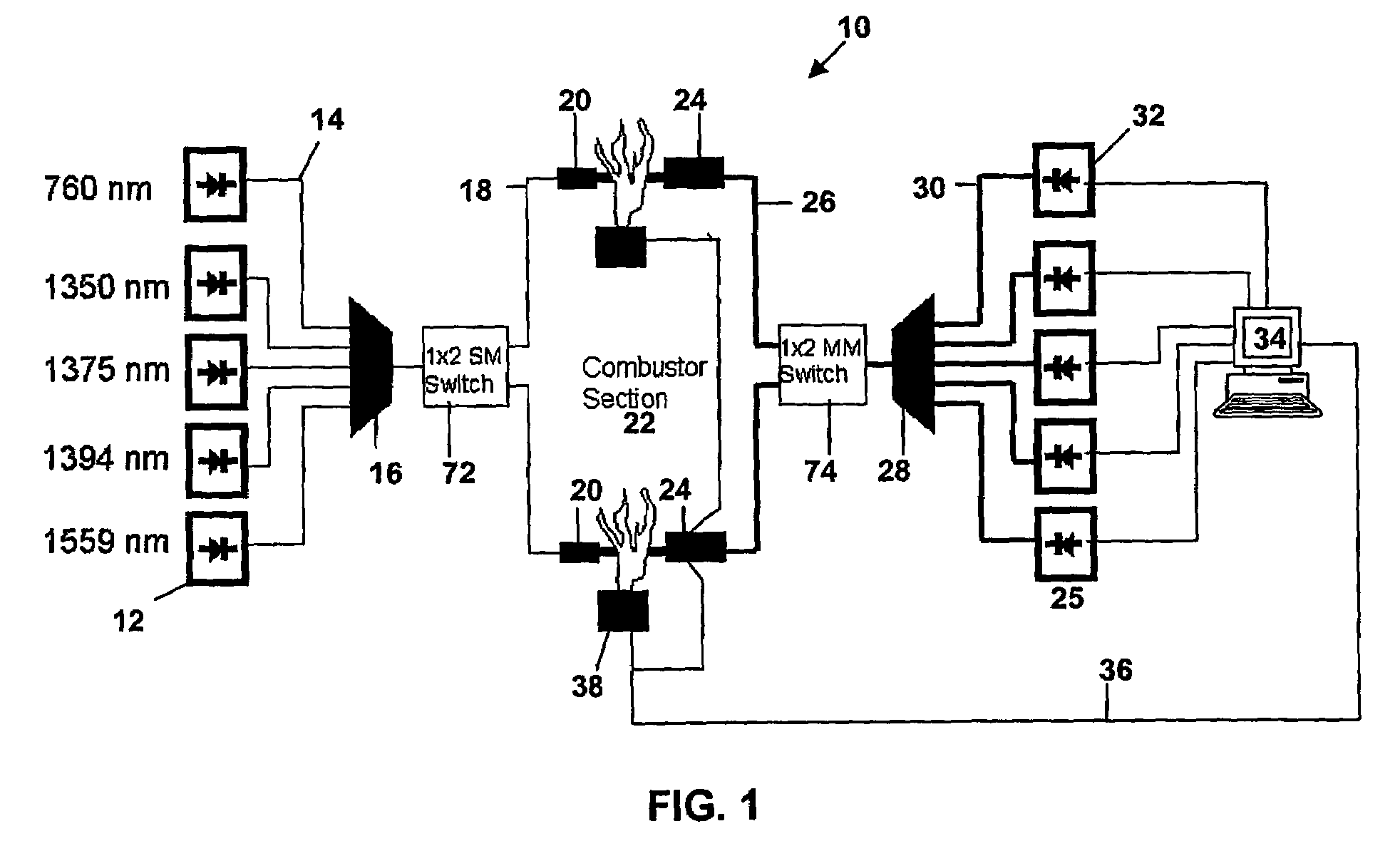
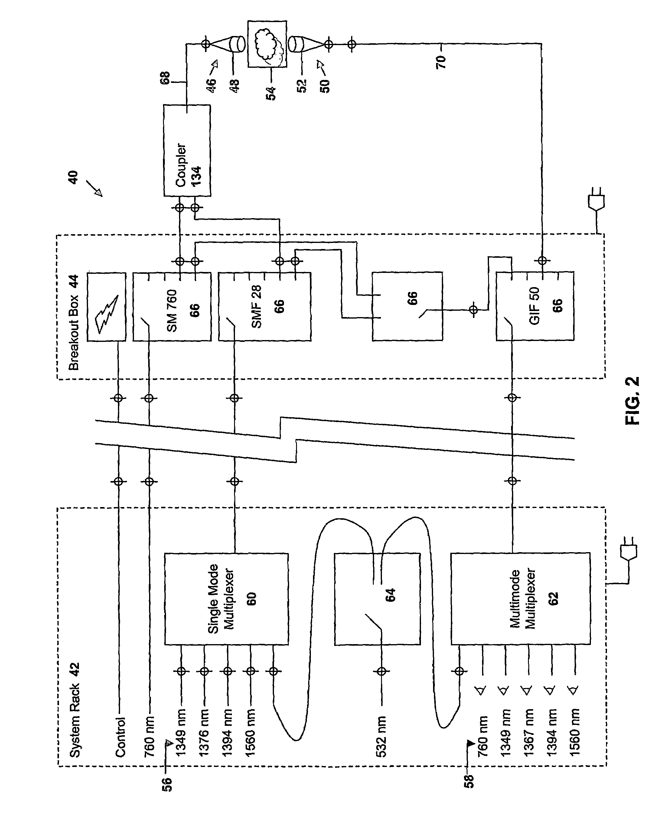
[0010]Optionally, the sensing apparatus may have the multiplexer optically coupled to fewer than all of the diode lasers and further consist of an optical coupler coupled to the output of the multiplexer and the separate output of any unmultiplexed diode laser. In such an optional embodiment, the optical coupler will optically communicate with the pitch optic through a select length of transmitting optical fiber. The length of the transmitting optical fiber may be selected to minimize mode noise. For example, the transmitting optical fiber may be implemented at a length of equal to or less than 3 meters, and be fabricated of Corning SMF 28 optical fiber which will assure that wavelengths less than 1240 nm, in particular 760 nm, do not become multi-modal during transmission through the transmitting optical fiber.
[0011]The sensing apparatus may also consist of means to mechanically manipulate a section of the catch side optical fiber to minimize catch side mode noise. One example of an appropriate means to mechanically manipulate a section of the catch side optical fiber consists of a motor having a shaft parallel to the longitudinal axis of the catch side optical fiber which is attached to the fiber and provides a twisting motion around the longitudinal axis. The twisting motion may consist of a sweep through plus 360 degrees and minus 360 degrees at a rate of at least 10 Hz to effectively average the transmitted signal and thereby reduce catch side mode noise.
[0012]Optionally, the sensing apparatus may further consist of a catch side alignment mechanism associated with the catch optic providing for the alignment of the catch optic with respect to the direction of the projection of the mutliplexed laser output. The alignment mechanism may increase the quantity of laser light received by the catch optic from the pitch optic and thereby coupled to the catch side optical fiber. The alignment mechanism may consist of an apparatus which allows the catch optic to tilt along a first axis and a second axis orthogonal to the first axis with both the first and second axes being substantially orthogonal to the direction of the projection of the multiplexed laser output. A stepper motor may be used to tilt the catch optic and a data processing system may be further associated with the catch side alignment mechanism and receive data from the detector related to the strength of the multiplexed laser output coupled to the detector and cause the catch side alignment mechanism to align the catch optic. Alternatively, a separate alignment beam may be projected to the catch optic and used as a reference for alignment purposes. A similar alignment mechanism may be implemented on the pitch side of the sensing apparatus to provide for alignment of the pitch optic and adjustment of the direction of the projection of the multiplexed laser output.
[0016]Another aspect of the present invention is a pitch side optical system for use in diode laser spectroscopy consisting of more than one diode laser having select lasing frequencies with each diode laser being coupled to an end of a distinct input optical fiber. The pitch side optical system further consists of a multiplexer optically coupled to the other end of less than all of the input optical fibers with the multiplexer outputting multiplexed laser light to a pitch side optical fiber. Typically, the diode lasers and multiplexer will be housed in a climate controlled room situated remotely from the combustion process chamber. The pitch side optical system further consists of a coupler optically coupled to the far end of the pitch side optical fiber and the far end of an unmultiplexed input optical fiber with the coupler combining the multiplexed laser light and the unmultiplexed laser light and outputting the combined light to a transmission optical fiber. Typically, the coupler is located near the combustion process. The pitch side optical system further consists of a pitch optic coupled to the transmission optical fiber. Typically, all optical fibers used in the pitch side optical system are single mode optical fibers. The length of the transmitting optical fiber may be selected to minimize optical noise. In particular, if laser light of relatively shorter wavelengths, for example 760 nm, had been multiplexed with laser light of relatively longer wavelengths, for example 1240 nm-5200 nm, and such a multiplexed beam had been transmitted in a suitable commercially available telecommunications optical fiber which did not exhibit a high rate of bending and other transmission losses over the entire transmitted spectrum, the relatively shorter wavelengths may have become multimodal over an extended distance. Thus, the transmission fiber length may be selected to minimize the creation of mode noise. For example, a transmission fiber length of 3 meters or less, with the transmission fiber being Corning SMF 28 optical fiber, can transmit laser light with a wavelength of 760 nm from the coupler to the pitch optic without the introduction of significant multi-modal behavior.
[0017]Another aspect of the present invention is a catch side optical system for use in diode laser spectroscopy consisting of a catch side optic optically coupled to a catch side multimode optical fiber and means to mechanically manipulate a section of the catch side multimode optical fiber to minimize catch side mode noise. The mechanical manipulation may consist of twisting the catch side multimode optical fiber around its longitudinal axis. The means to mechanically manipulate the section of the catch side multimode optical fiber in the above fashion may consist of a motor associated with the catch side multimode optical fiber such that a section of fiber is held fast relative to a shaft position of the motor and the motor shaft is repetitively swept through +360 degrees and −360 degrees of motion. The frequency of the motor shaft sweep may be at least 10 Hz to enable effective averaging of the transmitted signal and thereby reduce the effect of catch side mode noise.
[0019]Another aspect of the present invention is a method of aligning a diode laser spectroscopy gas sensing optical system. The method consists of providing an alignment beam of light, projecting the alignment beam through a process chamber, receiving the alignment beam with a catch optic, the catch optic being operatively associated with the process chamber. The method further consists of optically coupling the alignment beam from the catch optic to a detector through an optical fiber and determining the strength of the alignment beam coupled from the catch optic to the optical fiber. In addition, the method consists of aligning the catch optic to maximize the strength of the alignment beam coupled from the catch optic to the optical fiber. The method of aligning a diode laser spectroscopy gas sensing optical system may further consist of tilting the catch optic along a first axis and a second axis orthogonal to the first axis. Alternatively, the alignment beam may be projected by a pitch optic and the pitch optic may be aligned as well to further maximize the strength of the alignment beam coupled from the catch optic to the optical fiber.


